This project was inspired by Willem Pennings. I really liked the idea of having one of these as a desk toy, and wrongly assumed it couldn't be too difficult. I worked on it on-and-off for about a year since work was very busy, but I think it turned out very nice! I made some fairly significant design changes from Willem Penning's design (completely different electronics, smaller overall dimension, smaller motors). It ended up costing me about $1,500 in the end, which is more than I would've liked to spend, but it was a fun project. Most of the cost is in the motors and controllers, which were about $700 overall.
This post will focus less on the design and more on the mill/lathe work that I did as well as the controls that I developed. I did all of the machining/electronics work myself to save on cost.
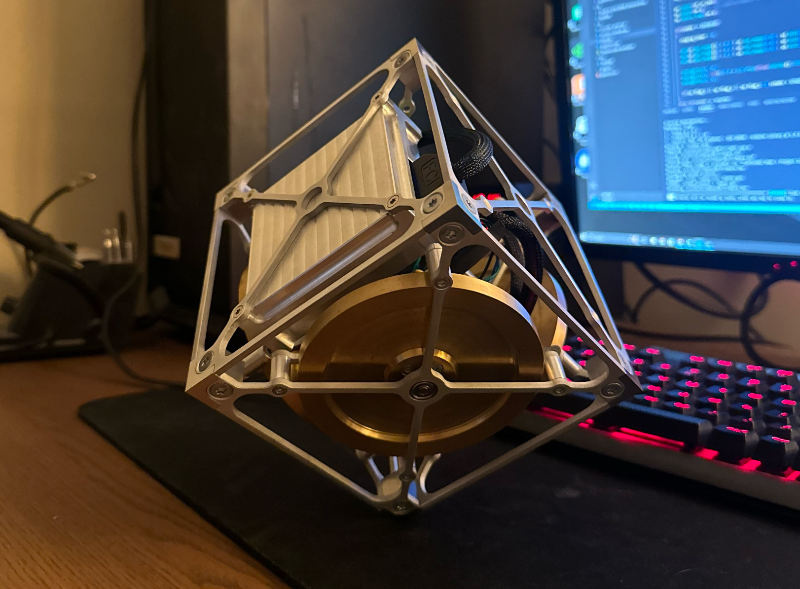
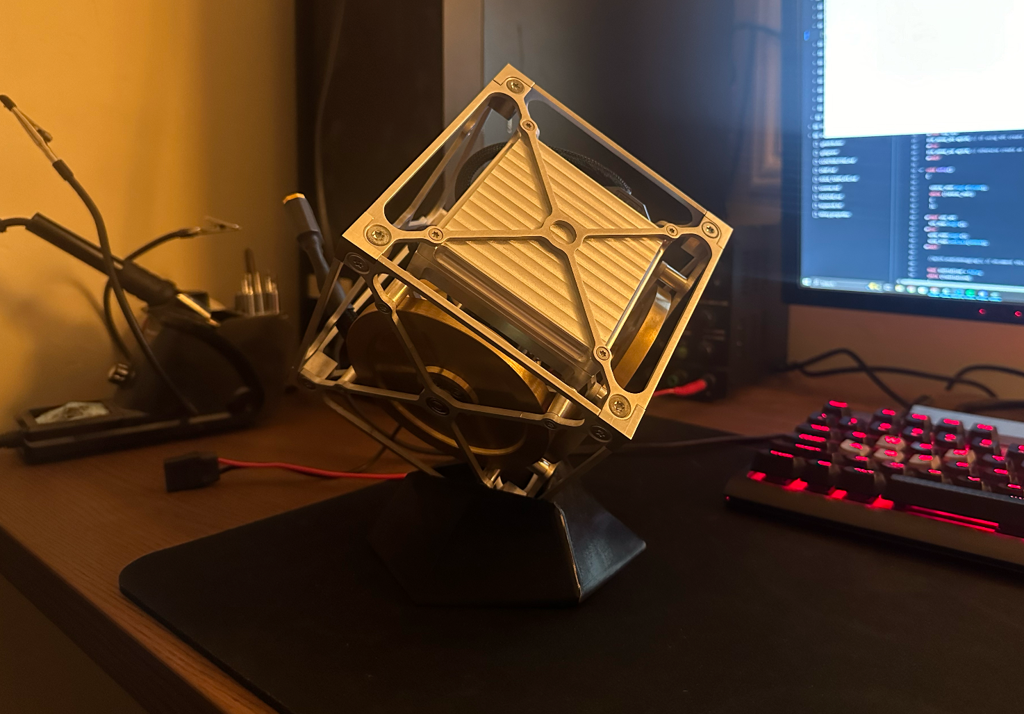
Balancing on my desk!
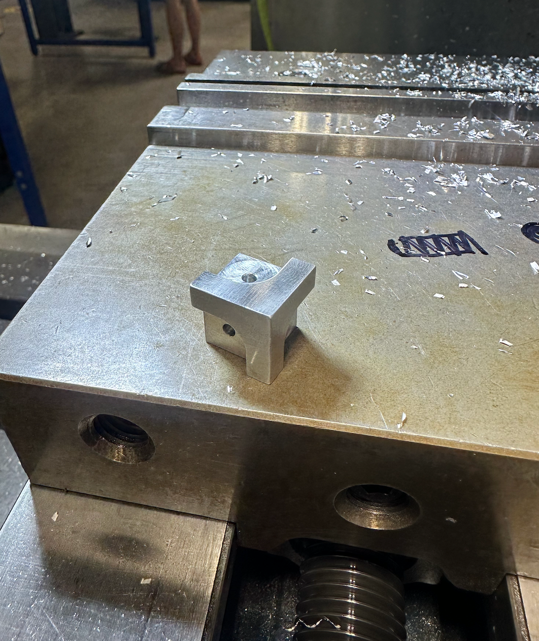
Cornerstone Manufacturing
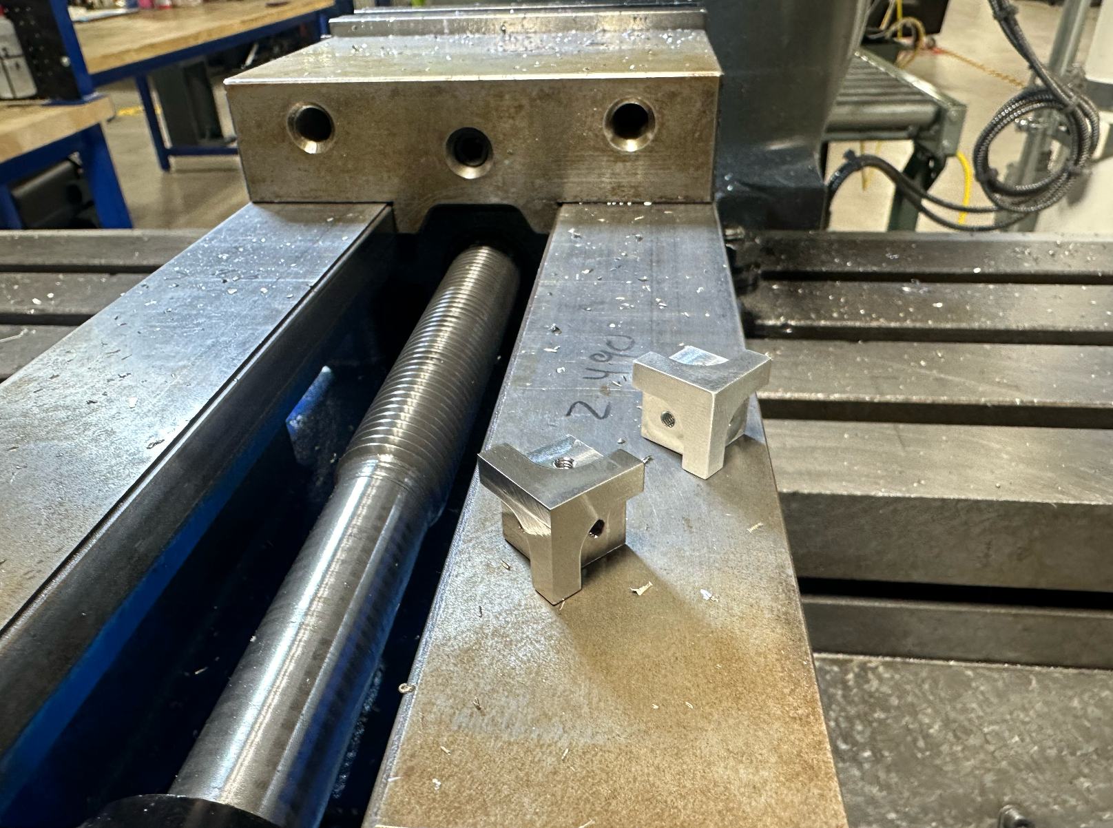
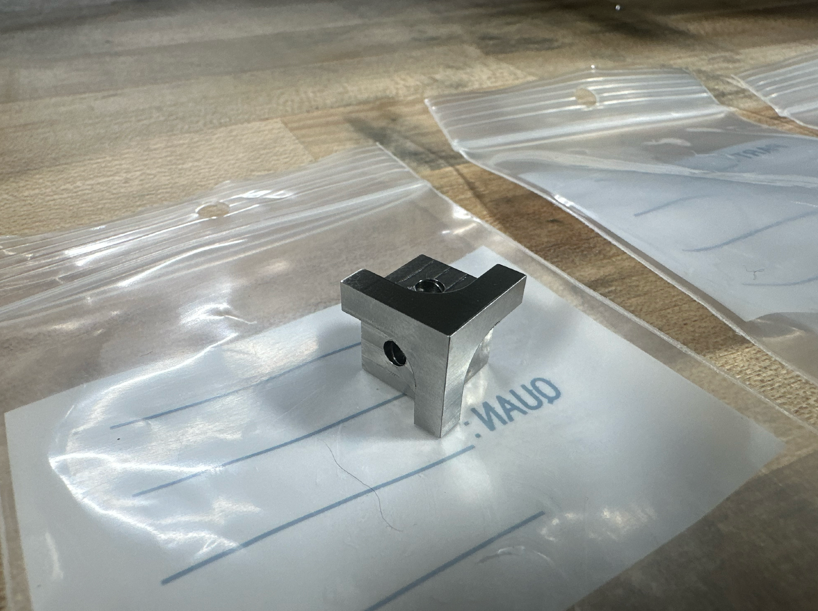
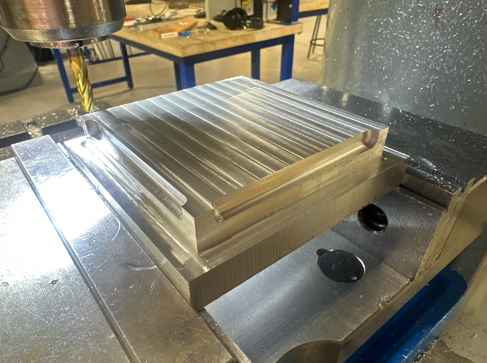
The cornerstones are made out of 316 stainless. I wanted something tough enough that the sharp corners would not dull over time balancing. Balancing on a sharp corner looks a lot more impressive than balancing on a radius.
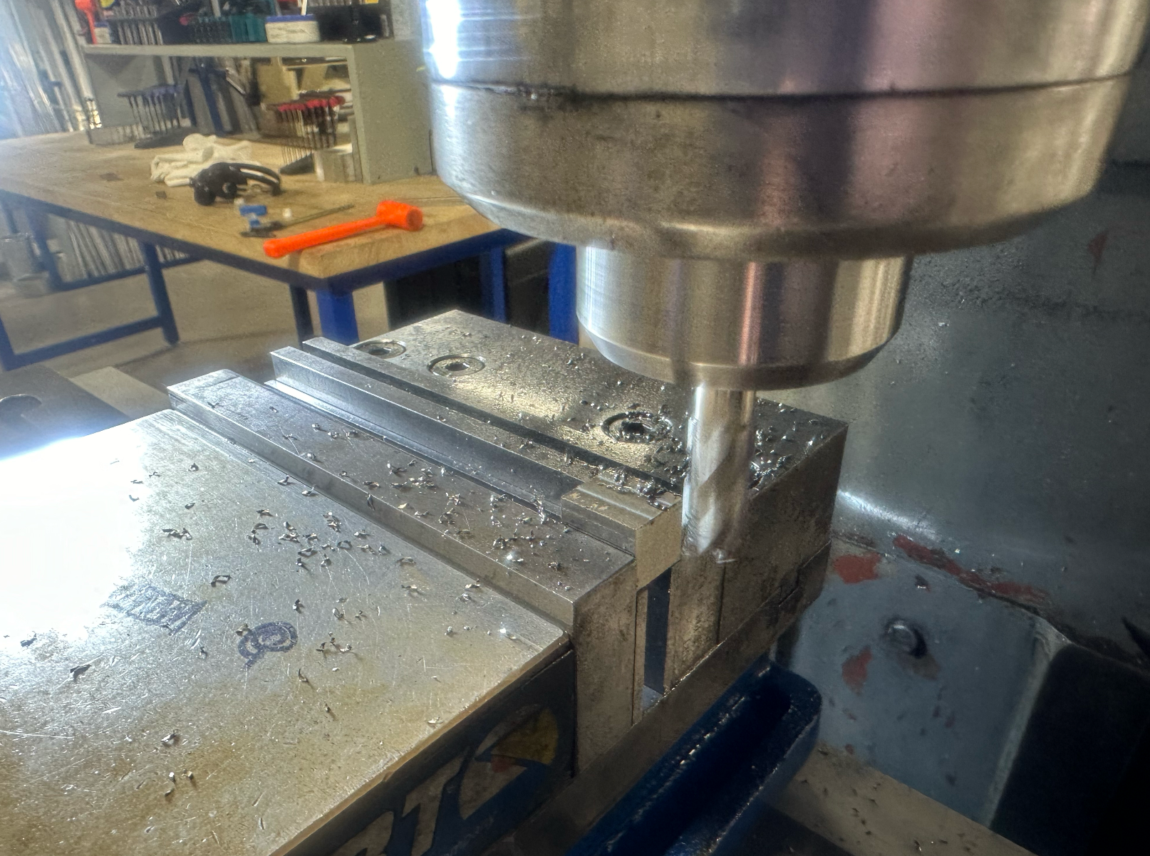
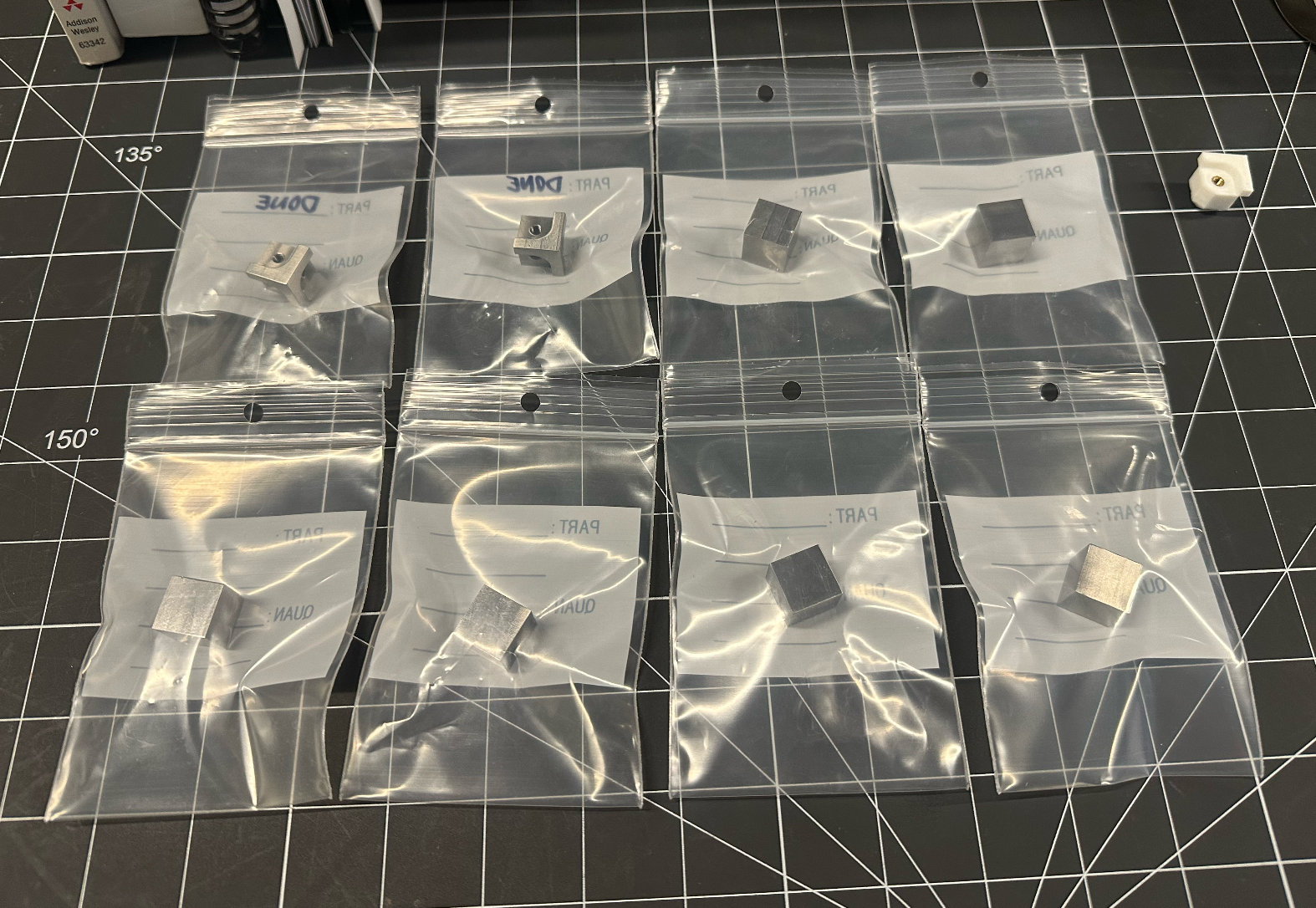
I started with a piece of 6000-series aluminum stock to get an idea of what the order-of-operations would be on the mill. After finishing one, I moved onto prepping and squaring the stainless stock into cubes. From there, I machined the grooves for the faceplates, and tapped the centers to M4x0.7. After breaking a tap on the very last part and having to re-machine one, I finally had all eight cornerstones finished.

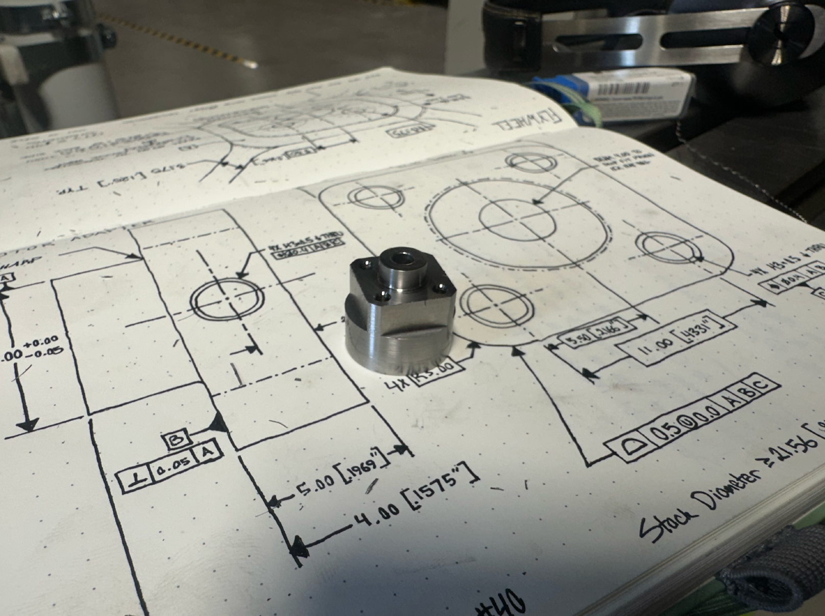
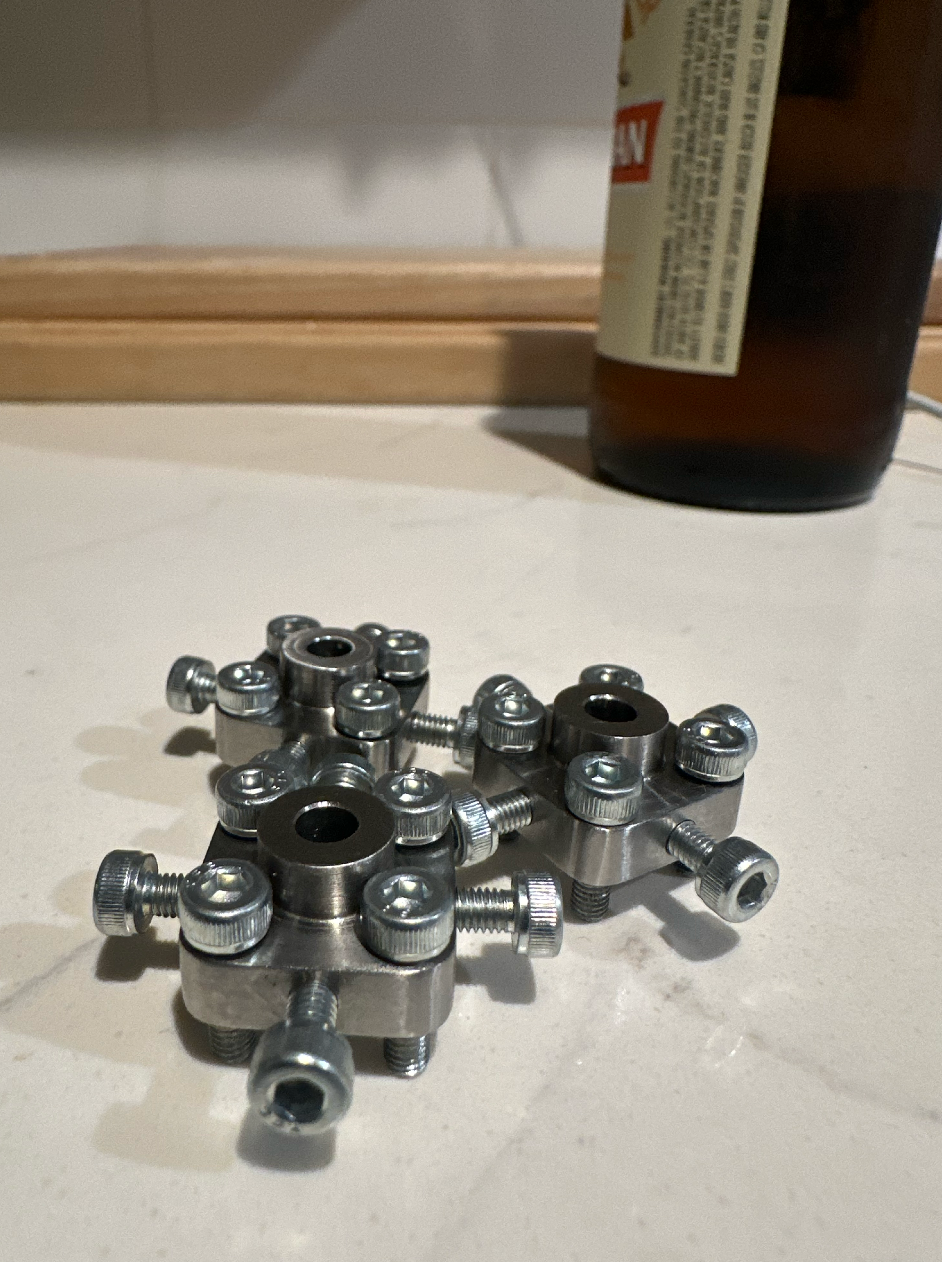
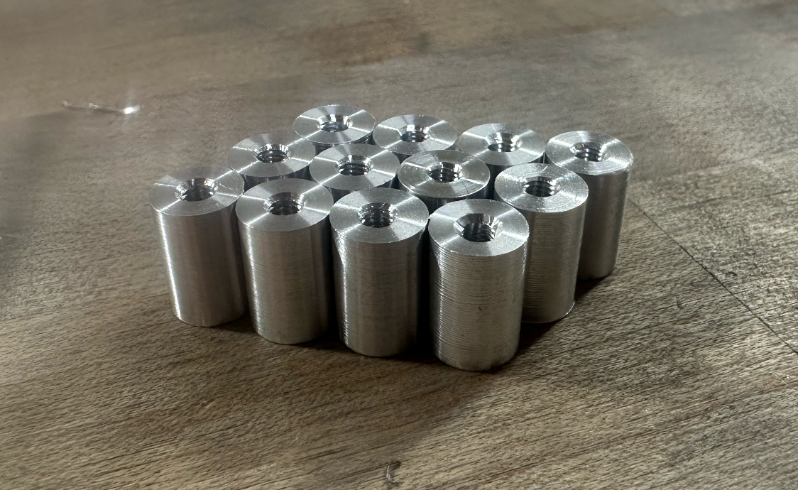
Motor Adapter Manufacturing
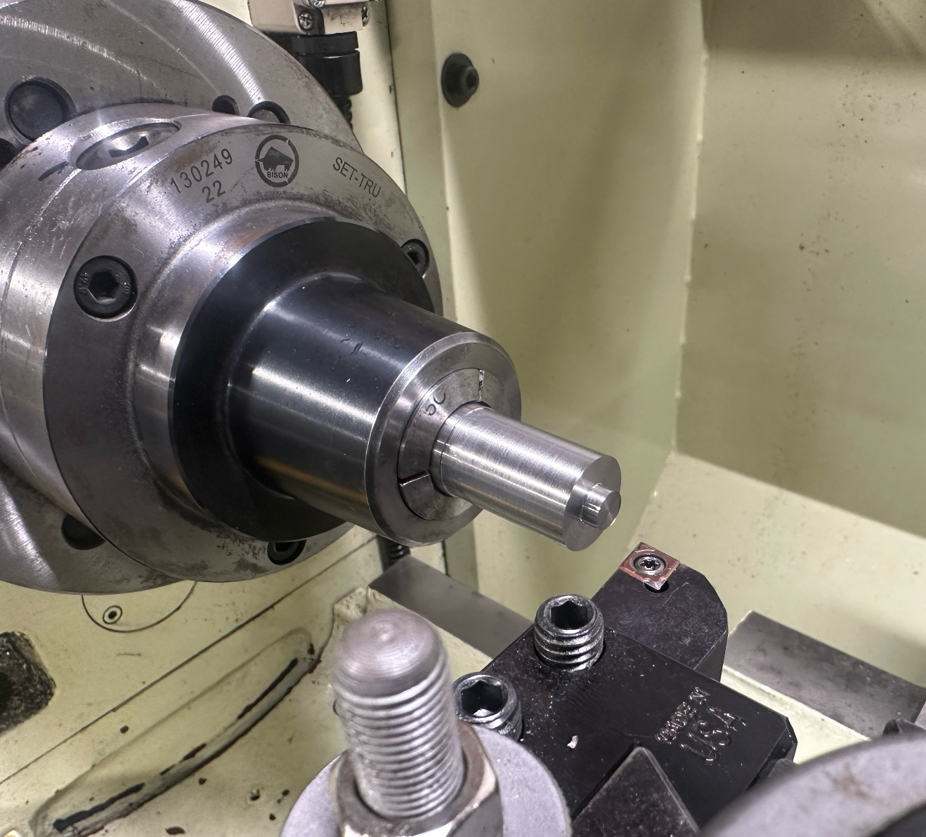
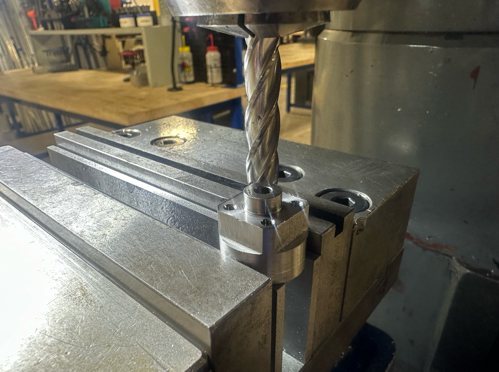
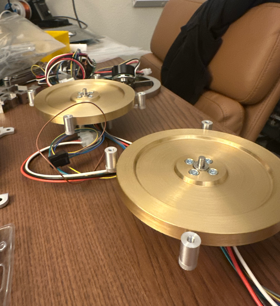
The motor adapters are also made with 316 stainless. The center is reamed to 4.00 to fit over the motor output shaft, and there are four radial threaded holes to receive set screws. The four axial threaded holes used to mount the flywheels, which are piloted on the cylindrical outer surface.
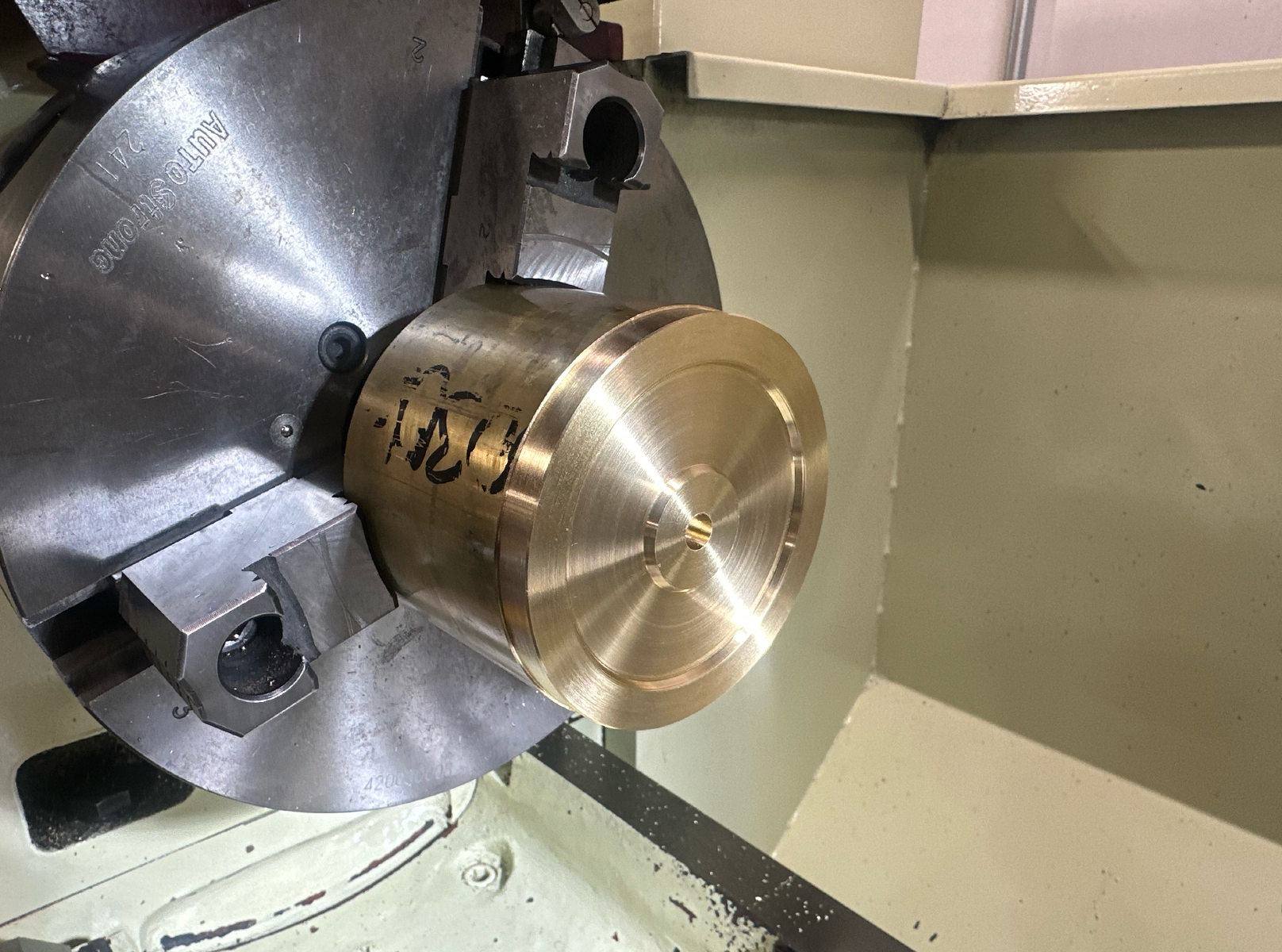
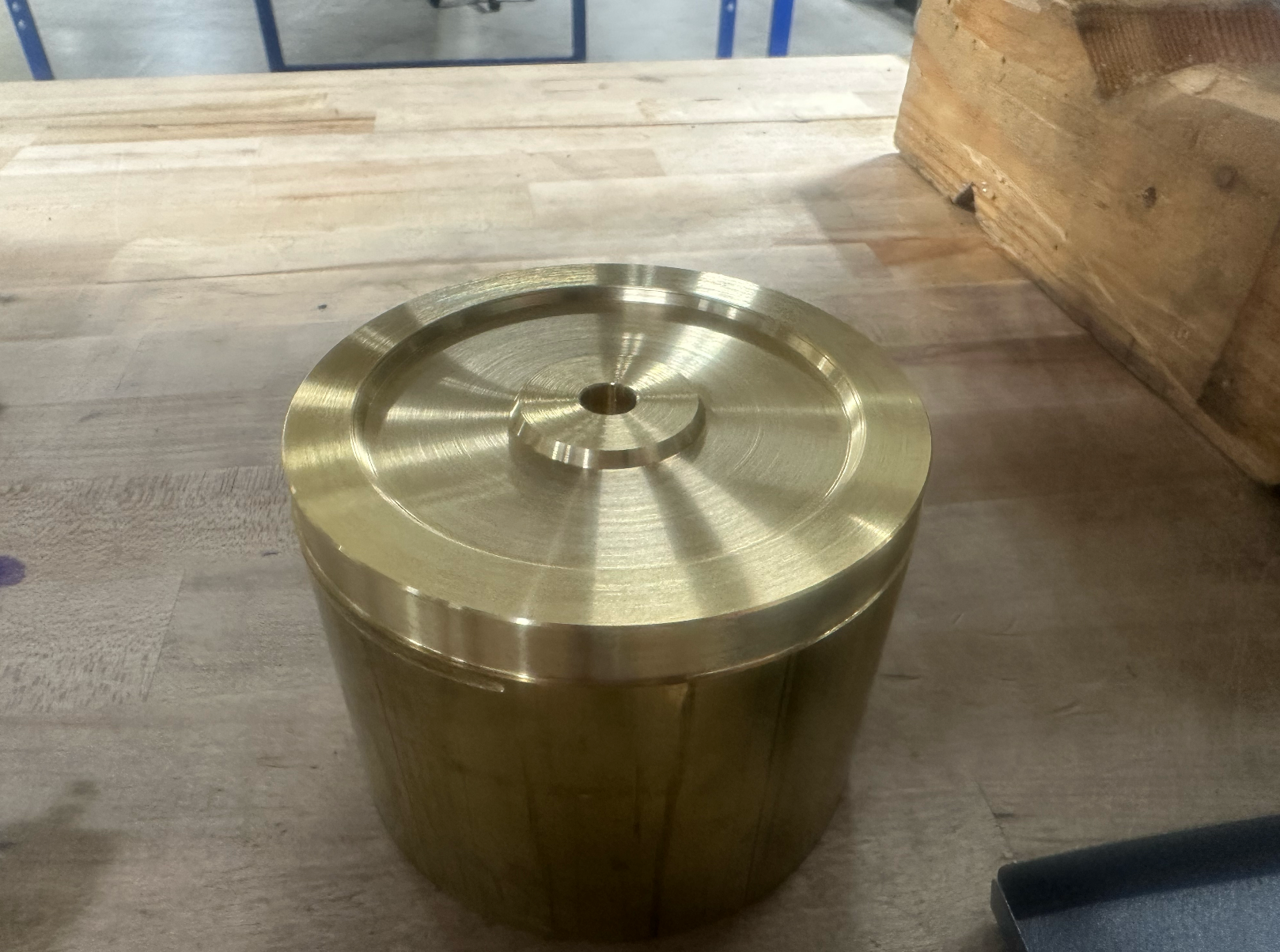
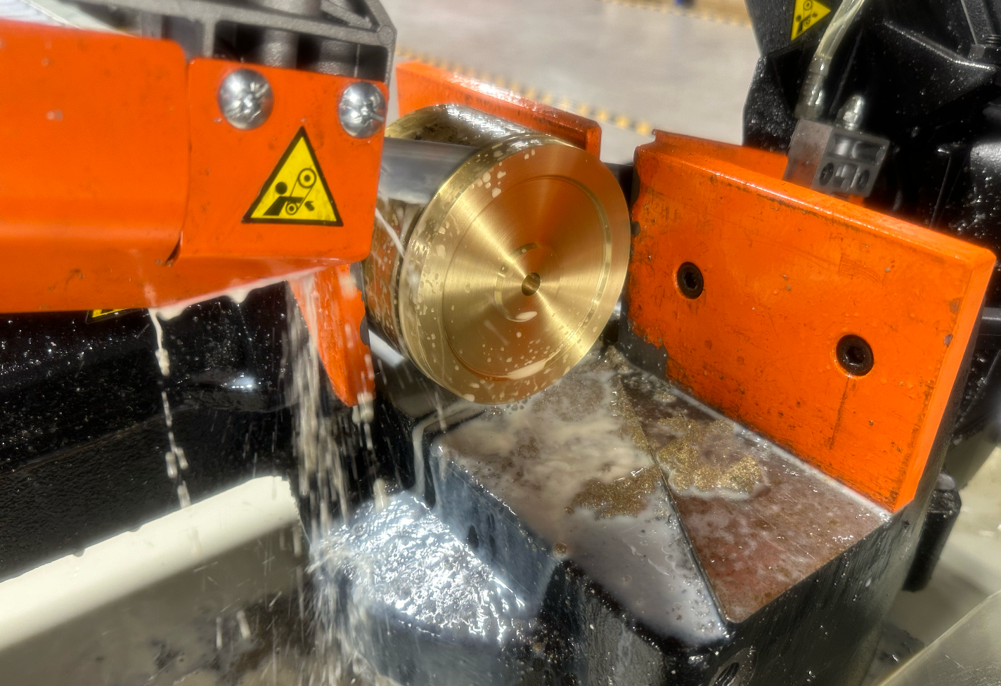
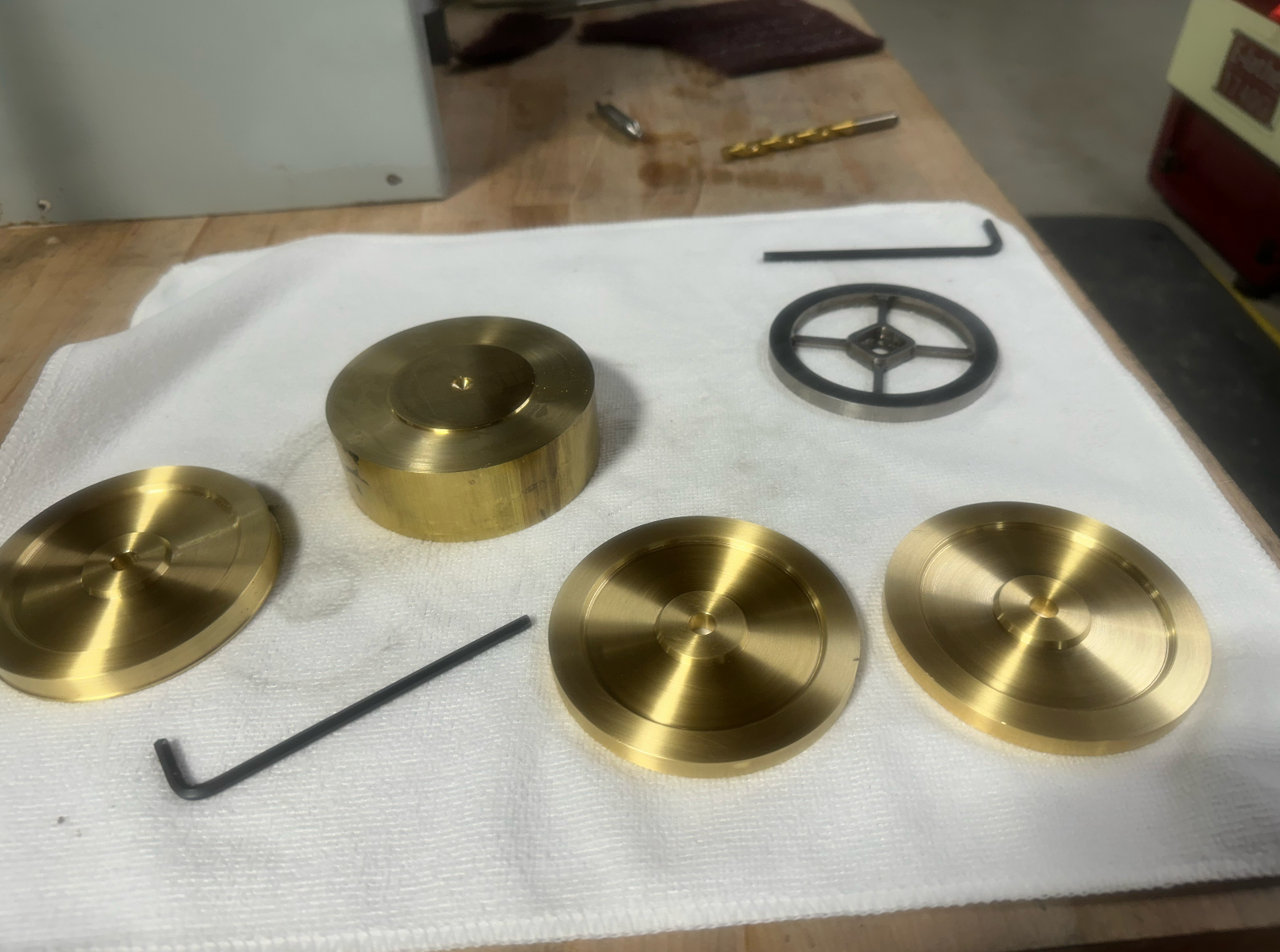
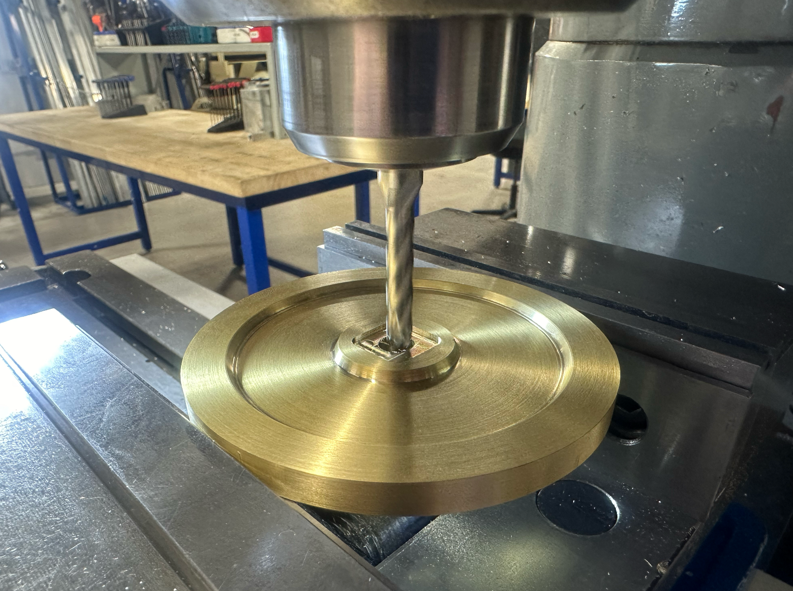
Flywheel Manufacturing
The flywheels were really fun. These were turned from 360 brass stock, and then post-machined on the mill for the features to accept the motor adapters. They are quite a bit heavier than strictly necessary, but it allows them to spin extraordinarily slowly while the cube is balancing. Because there are no ribs/speed holes, it doesn't appear that anything is moving at all while the cube is balancing. Turning the material was a breeze, but parting it off was a nightmare. The large diameter aside, the material is very gummy and work-hardens easily. I ended up removing the stock from the lathe and cutting it with a horizontal band saw before flipping it over to do the opposite side.
The Other Bits and Pieces
The remainder of the cube consisted of aluminum standoffs that were made on the lathe and a few sheet-metal brackets and faceplates that I ordered from send-cut-send. I tried to make the flywheels out of sheet metal too, and then post-machine them on the lathe, but I wasn't happy with the rough surface produced by the water-jet on the internal edges. The faceplates were countersunk to allow for flush fasteners and reamed on the bearing interfaces.
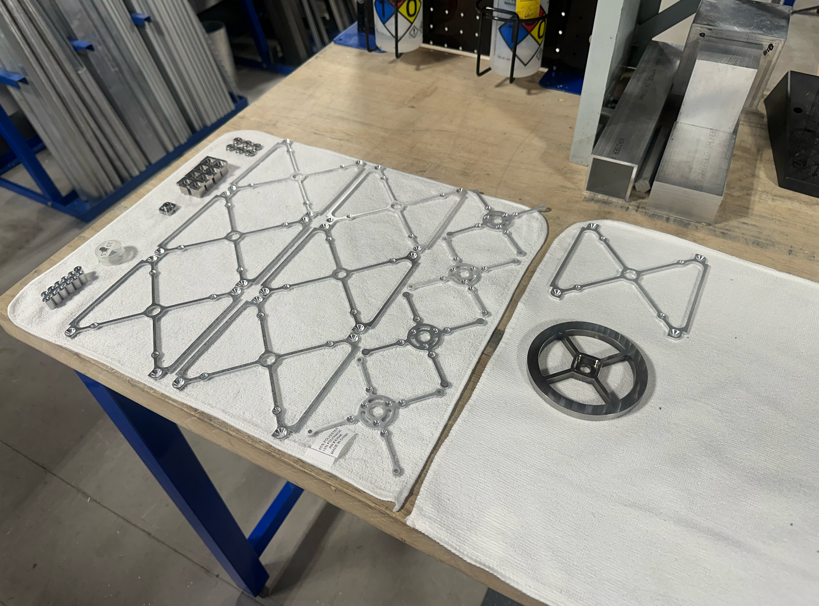
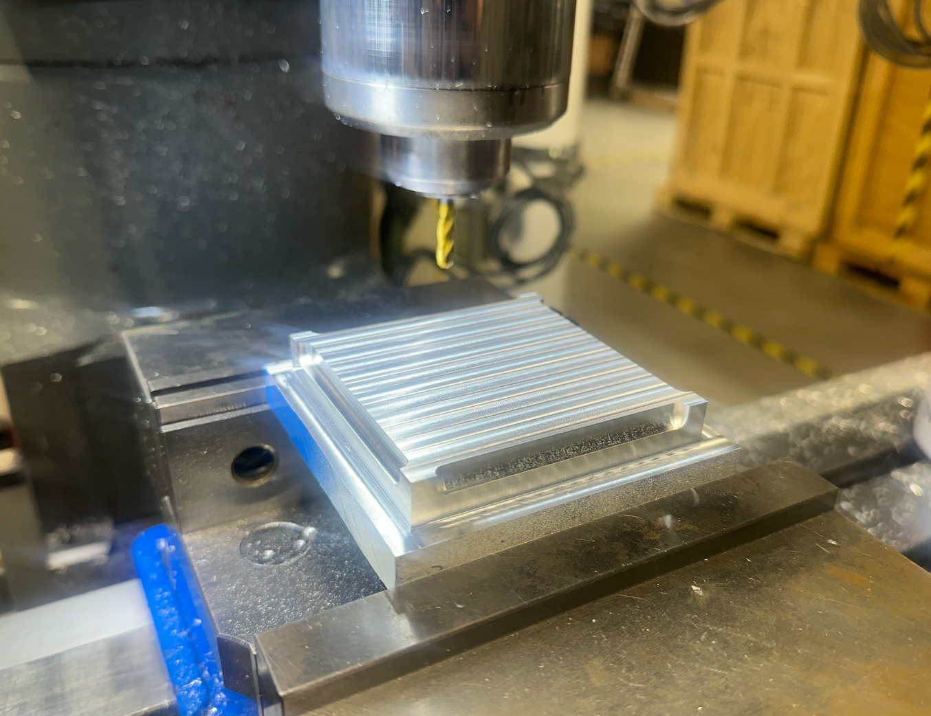
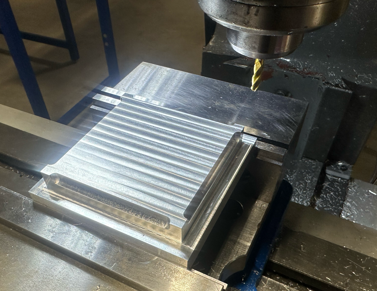
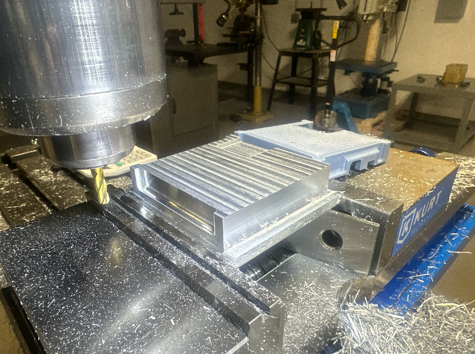
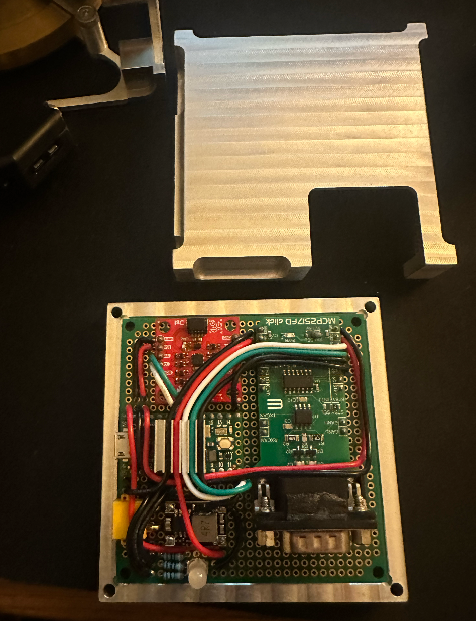
Electronics Enclosure Manufacturing
These were fun parts too. They are about 1mm in thickness and are manufactured out of 6000-series aluminum. This enclosure was more or less to protect the electronics from dust, but it is not sealed. It adds a bit of unnecessary weight, but I think it looks nice.
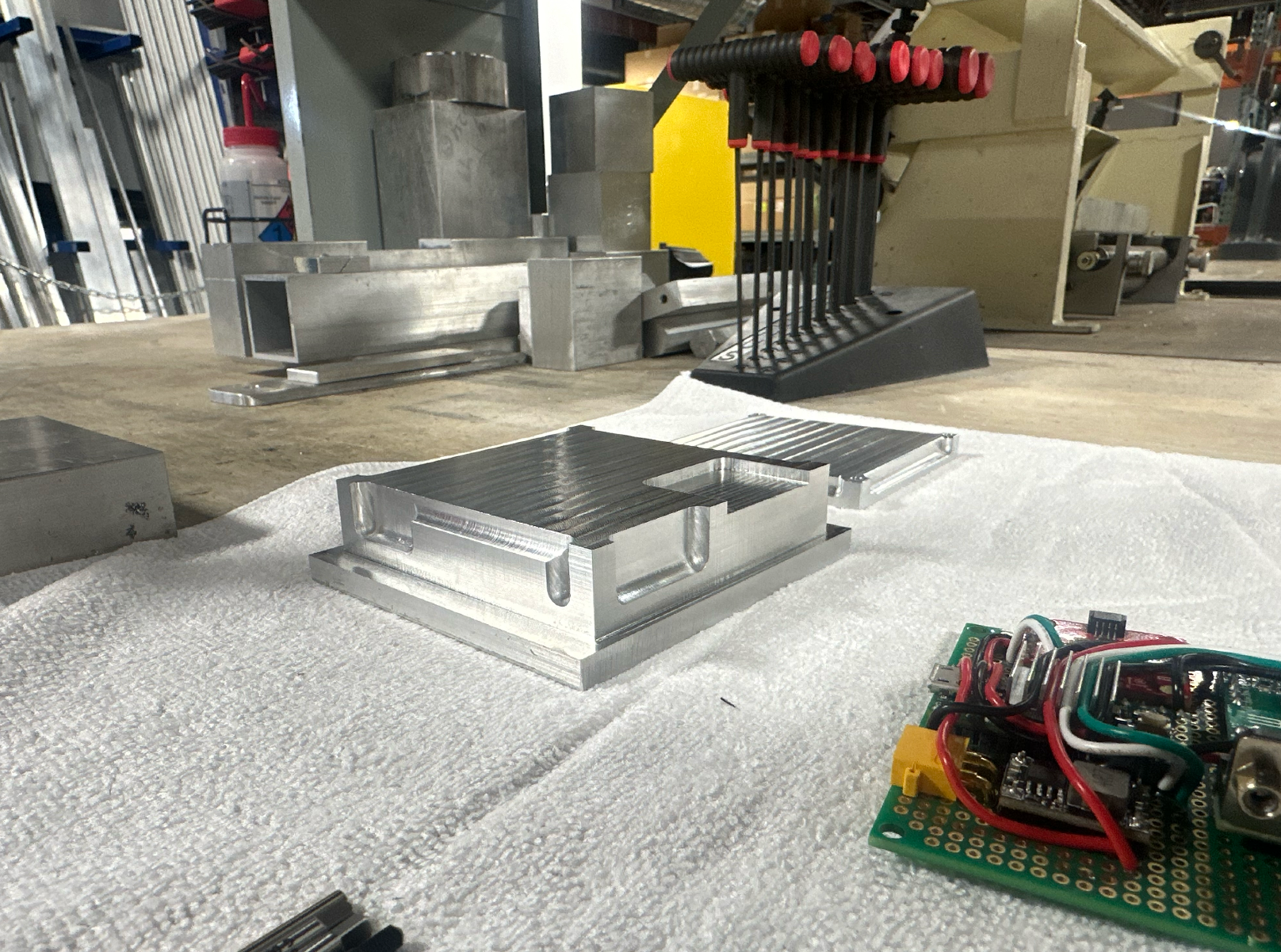
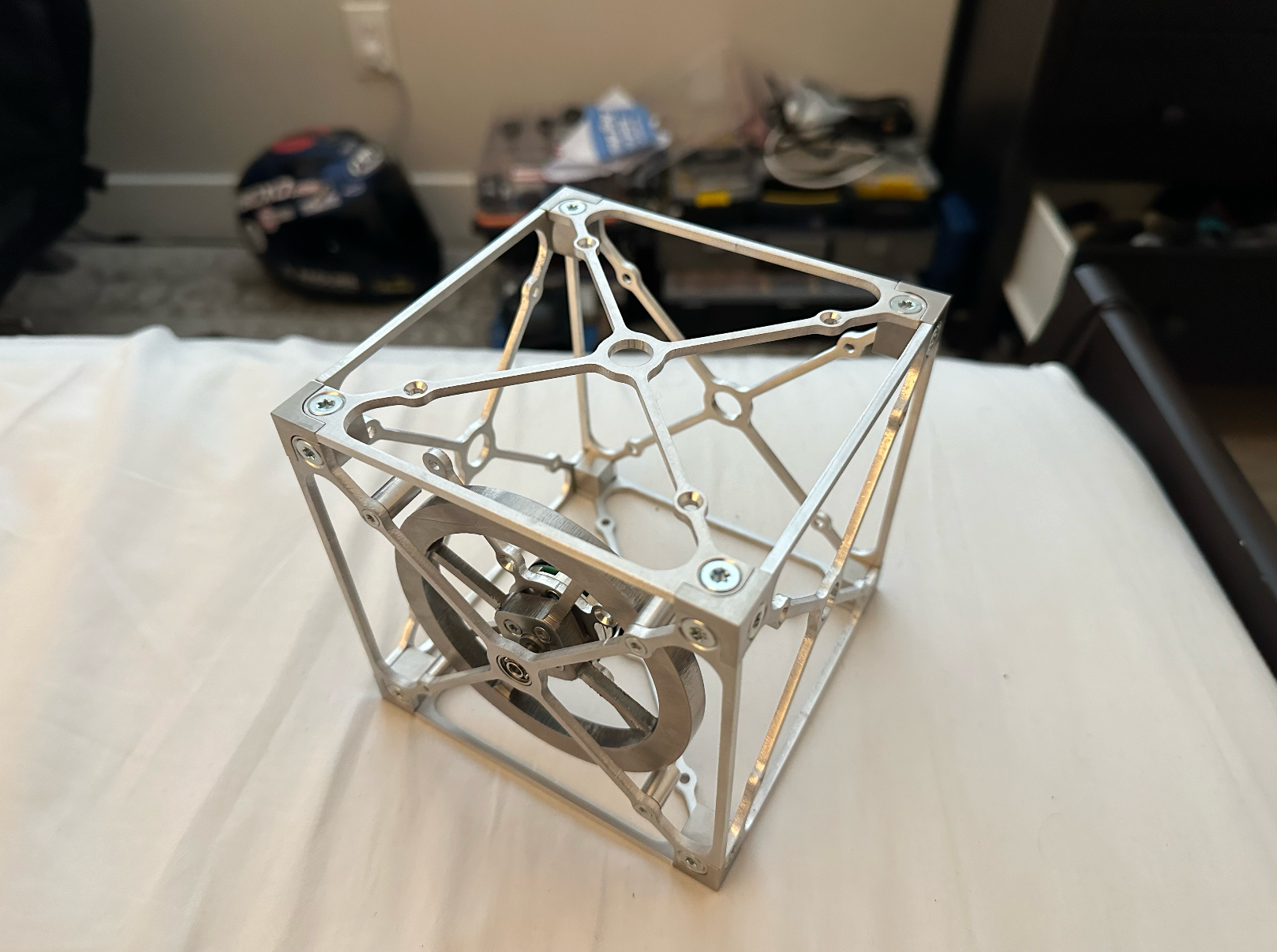
Assembled Cube on a 3D-printed Stand
This is the assembled cube! Assembly was fairly straightforward. The electronics are made up of a Teensy 4.0, a MCP2517FD CAN transceiver, and a cheap Sparkfun IMU.
IMU Sensor Fusion and Quaternion Estimation
The first step to getting it balancing was making sure the cube knew how it was oriented. The IMU comes with a quaternion output mode, but in all honesty, it is extremely poorly documented and I had a lot of trouble figuring out what was going on with the faulty internal drift compensation. The message below, from the creator of the library, didn't inspire much confidence either:

The internal sensor fusion algorithm (named "DMP" or digital motion processor) was smooth but seemed to place too much gain on the gyroscope data, and I couldn't figure out how to adjust these gains or get the internal drift correction to work right.
As a result, I decided to write my own sensor fusion algorithm. The accelerometer, when calibrated, provides a very accurate long-term orientation reference, but it doesn't capture slight, rapid changes in angle very well and can be unstable. The gyroscope, on the other hand, is fantastic at capturing these slight angle changes, but is subject to lots of noise and drifts over time. By modeling the orientation with the accelerometer as a steady-state goal and the gyroscope as a "disturbance," the advantages of both sensors can be taken into account. Practically, this looks like an estimation where the gyroscope does the bulk of the estimation through dead-reckoning (integration of gyroscope data), and the accelerometer continuously biases this estimation towards the measured orientation value to compensate for gyroscopic drift.
In order for this to work well, I also implemented a calibration procedure. The cube is placed on all six faces and accelerometer data is normalized and offset to +/- 1g to correct for accelerometer raw data issues. Before each balance, 1000 samples of gyroscope data are also taken over the course of a second and averaged to calculate and reduce drift in each axis.
With a little bit of math and a lot of trial and error flipping signs, this yielded me a quaternion that describes the orientation of the cube. I wrote a little visualization tool in PyGame to help with debugging, and it shows the result of this work.
I spent quite a bit of time trying to speed up the algorithm through small-angle approximations and adjusting IMU sample rates, until I was happy with the data rate. I don't have an exact number, but it's on the order of thousands of measurements per second, which I figured was sufficient for my needs.
Controller Hookups and Spin Testing
Now that the cube knows where it is, I wanted to get the flywheels going. What a nightmare this was. The controllers themselves (moteus-c1), made by Josh Pieper at mjbots, were extremely straightforward. They use a small diametric magnet on the back of the motor to get an absolute rotor position reference, which is used to do FOC control, allowing for very slow-speed operation. The libraries written by Josh are well-documented, and extremely easy to work with.
The interface between the controller and the Teensy was the pain. I diagnosed SPI issues, CAN issues, and more, reading through the forums. The documentation on the MCP2517FD was not very simple or straightforward, and I made a lot of mistakes in the process. Even after solving all of the problems, I still had spotty connections and sometimes the SPI bus would just randomly drop out.
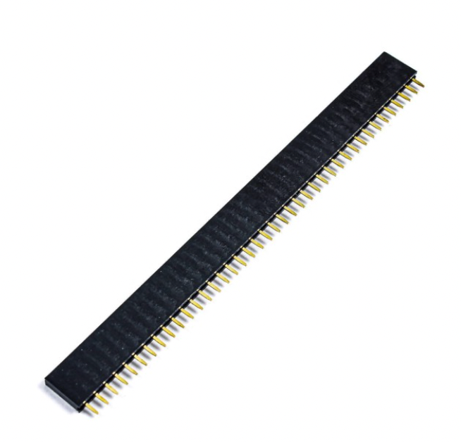
I diagnosed this, after almost a week of work, to the cheap 2.54mm prototyping board headers that I bought on Amazon. Yeah, these. I found that, on a lot of them, the wall separating the receiving pins was extraordinarily thin or broken through entirely, and soldering them to a board even at low temperatures would melt whatever wall was left and cause them to short. This manifested itself as a multitude of different problems depending on which pins were shorted, and the problem was completely intermittent, which made diagnosing the problem very difficult. Pain.
After buying higher-quality headers, all of the problems were gone and I was off to spin testing! Some videos attached below! These controllers had some quirks especially with configuration saving, which led me to (completely my fault) accidentally smoke up a motor in my bed, which smelled awful for multiple days. Once they were working though, the response was great and I was very impressed with the low-speed control.
Finally, the fun part! Everything was working mechanically and electrically, so now I just needed to do the software. Balancing took a lot of trial and error, but the actual algorithm is fairly simple. The next few paragraphs are kind of a book, and it is simpler to understand them by considering just the case of a cube balancing on its edge, with one flywheel.
Figuring out the controls
The "target" quaternion is calculated geometrically and sets the balance point. The error between this "target" quaternion and the "current" quaternion is the amount of error that the flywheels need to correct for. With some basic math, the angular error can be calculated for each axis. The response that I want out of the motor also depends on angular error rate, however, so the gyroscope values are pulled as well.
I tested this configuration, which is essentially a PD loop with angular error as the input and torque as the output. The cube balanced, but the flywheels would saturate quickly. I tried adding an integral term, tuning the gains, and a few other things, but the flywheels would always spin up until I ran out of voltage.
Basically, I had two goals that I had to solve for simultaneously -- minimizing motor speed and minimizing angular error. With only the PD loop on angular error, the cube would reach a steady balance point with no consideration of flywheel speed. Since a well-tuned PID loop does not overshoot, it never gives the flywheel an opportunity to spin back down. To solve this, I added PD terms on flywheel position. This seems unusual (a PD/PD loop on two different variables), but it really helps to solve for two different goals.
Suppose the cube is ever-so-slightly off-balance. It is forced to accelerate the flywheel to maintain balance, increasing the flywheel position quickly. Because there is now a proportional term on flywheel position, functionally, the "target" is adjusted so that the cube pushes itself over the tipping point, rather than approaching it slowly. This allows the flywheel to spin back down, since now the flywheel has to accelerate in the opposite direction. The derivative term on flywheel position (or flywheel speed) damps this deliberate oscillation, allowing the cube gently push itself over the balancing point, back and forth, allowing it to spool down the flywheels.
TLDR; the first P term (tilt error) does the majority of the work. the second P term (flywheel absolute position) helps to desaturate the flywheels and compensate for CG changes/estimation issues. the D terms damp the work of both of these to keep things from oscillating out of control.
The final control equation followed this form:
Torque = (k1*tilt error) + (k2*tilt error rate) + (k3*wheel position) + (k4*wheel velocity)
where k1, k2, k3, k4 are the associated gains.
Finale
And finally, it's balancing! It's not perfect, and has a bit of jiggle about the balance axis, but I'm happy enough with it to call this project done.
Balancing on the corner with minor disturbances
Balancing on the edge with an offset CG. The unused flywheels are automatically deactivated.