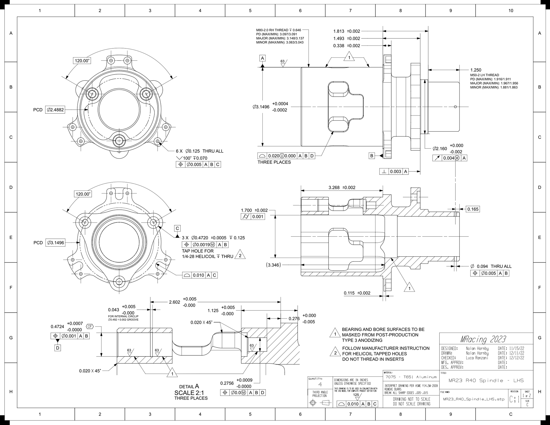
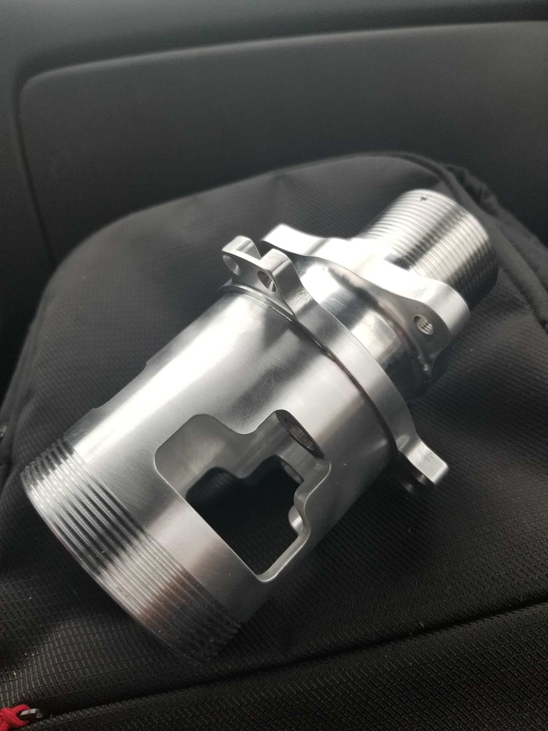
Drawing for the left-hand side spindle/planet carrier
The right-hand side spindle will have reversed threads for the center-lock wheels and bearing lock-nuts.
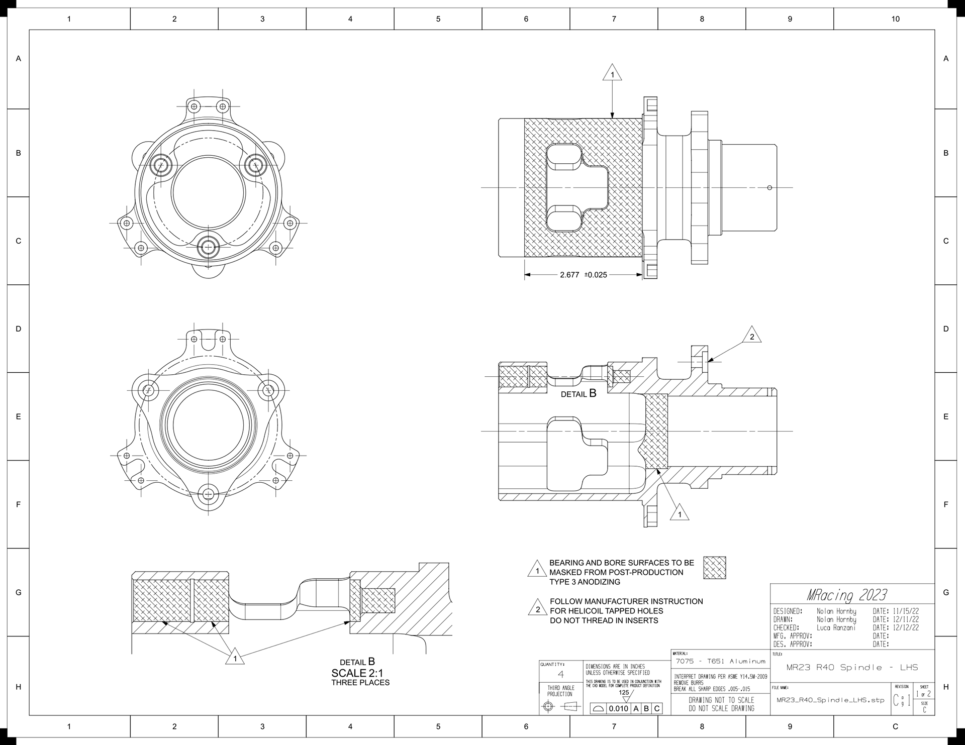
Masking drawing for the left-hand side spindle/planet carrier
Type 3 anodization builds up an oxide layer that will mess with the bearing surface tolerances, unless it is masked off or post-machined after-the-fact.
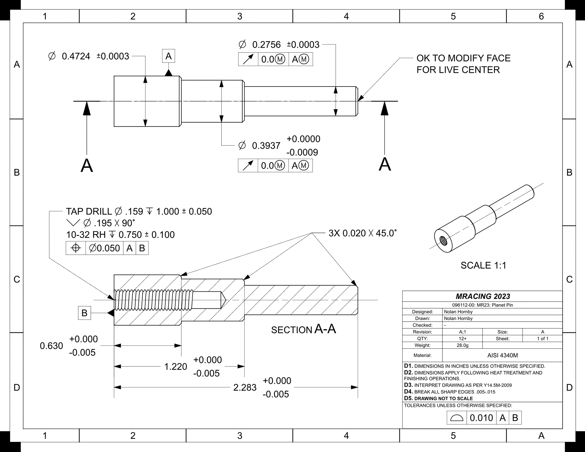
Drawing for the planet pins that support each of the planet gears
The pins are installed blind; the 10-32 thread was added there so it was possible to pull them back out.
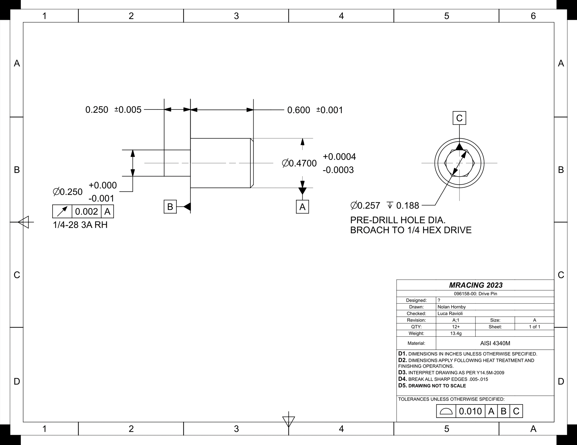
Drawing for the drive pins
The wheels are piloted onto the spindle with a circular interface, and these pins handle the torque loads. They are screwed into the spindle, but the load is transferred through a piloted portion of the .470" OD.
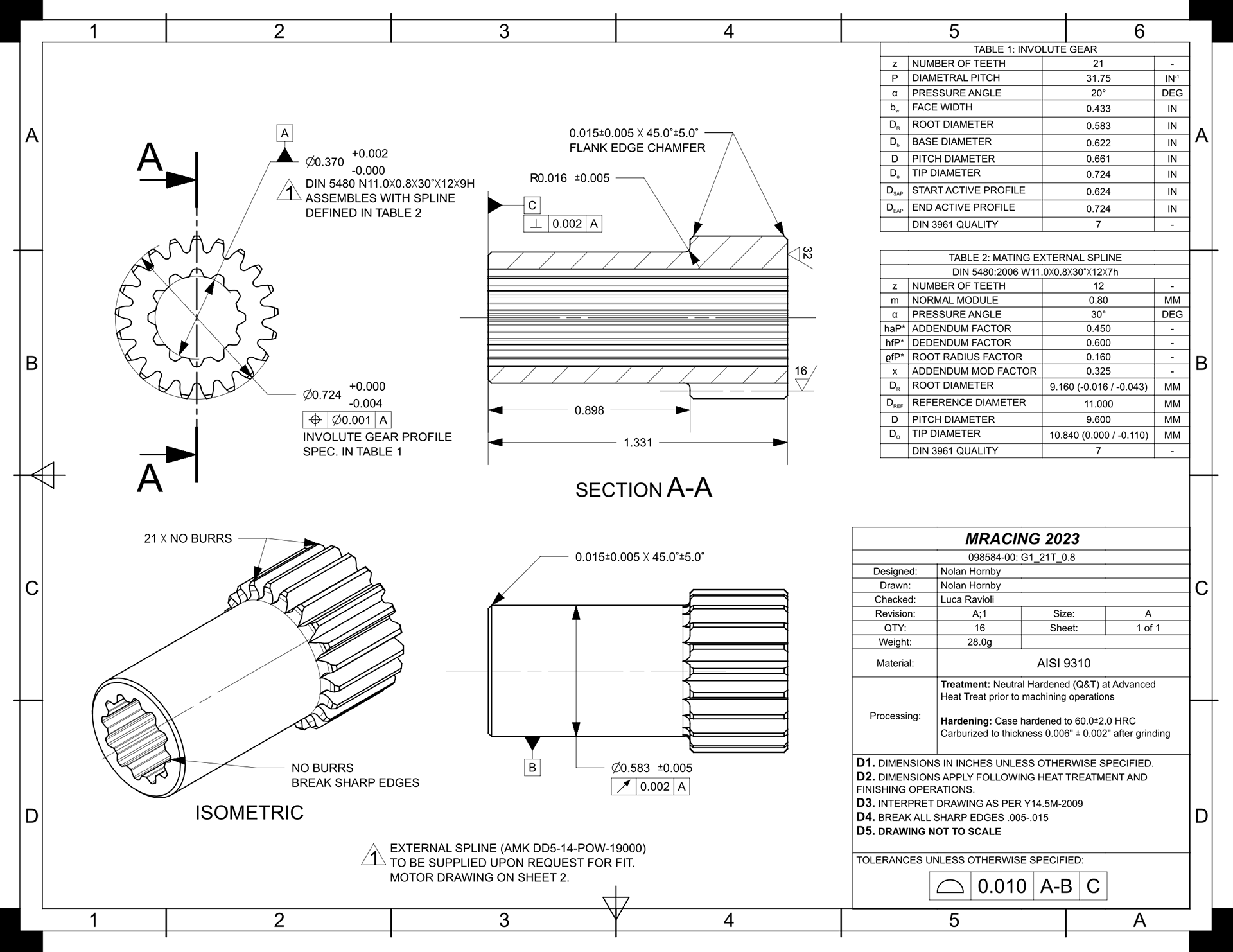
Drawing for the sun gear G1
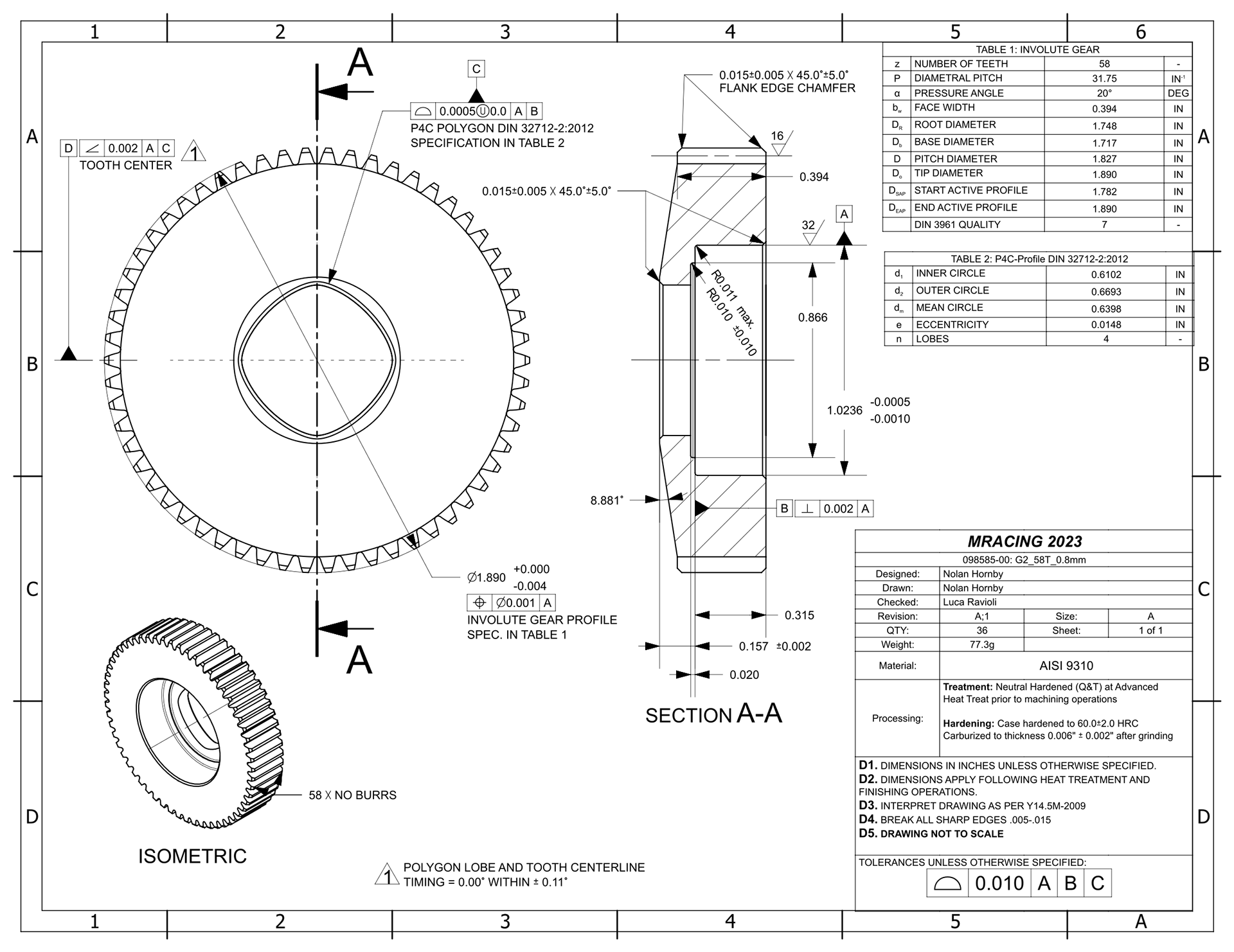
Drawing for inboard planet gear G2
The clocking of the spline to the profile of the teeth is tremendously important for this style of gearbox, and Luca and I spent a good amount of time making tooling required to reference the gear teeth when cleaning up this form. The polygonal spline was chosen as a shape that would be easiest for us to clean up post heat-treatment.
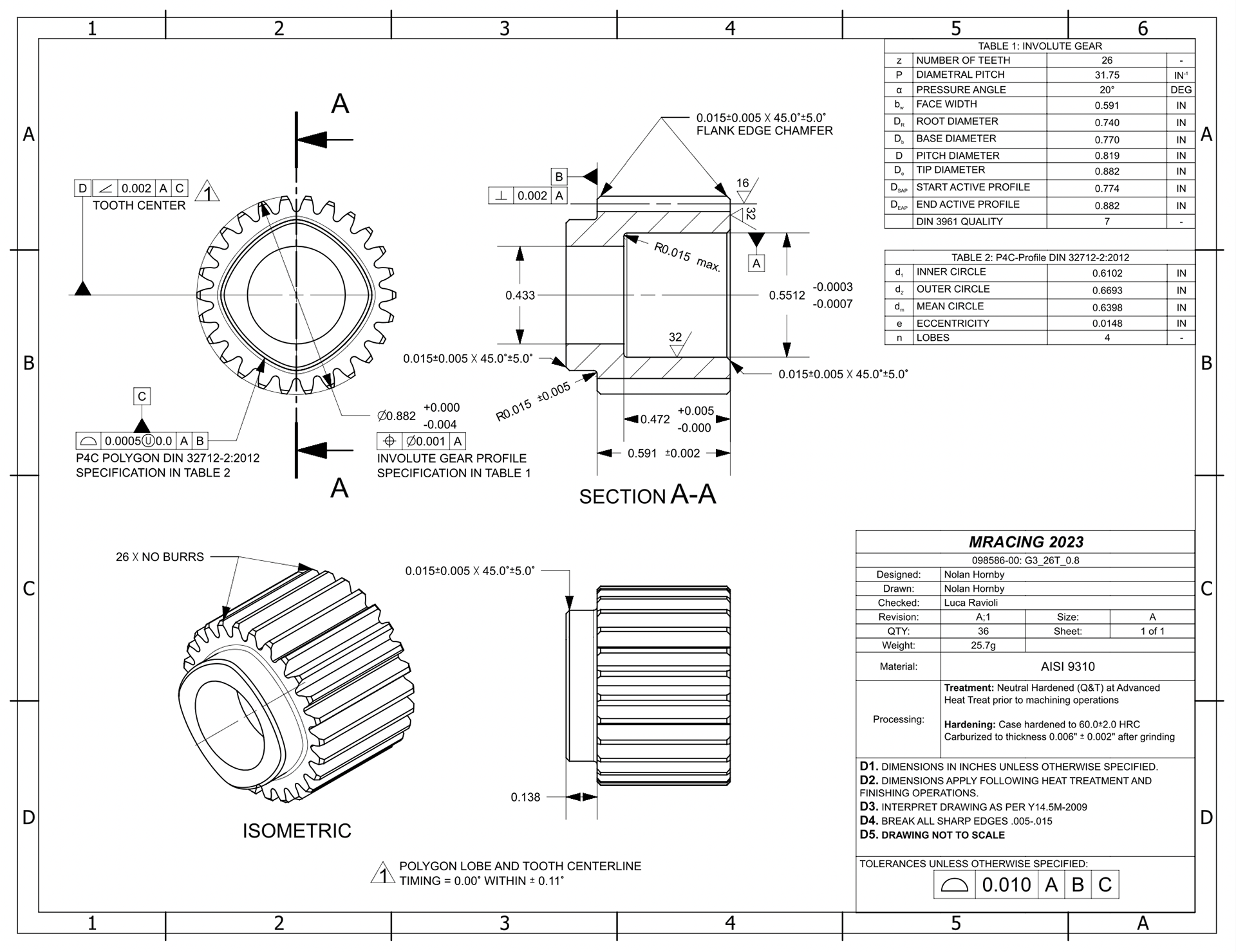
Drawing for outboard planet gear G2'
This part has the same challenges as that above, but is more difficult to fixture because it is so much smaller. We ended up figuring out a good strategy using clamping pins and fingers, and finished them all over the course of two days.
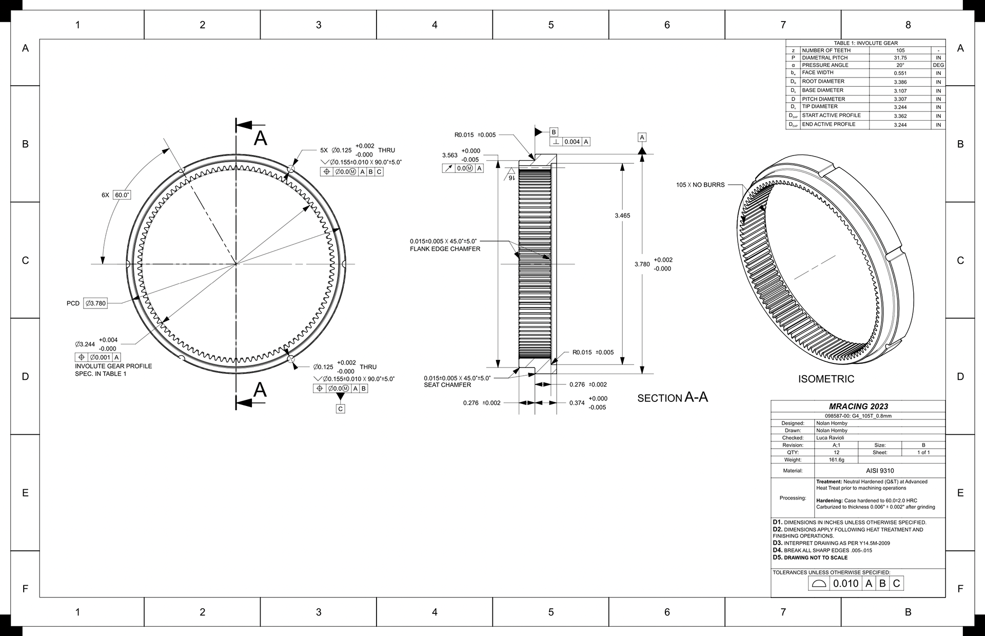
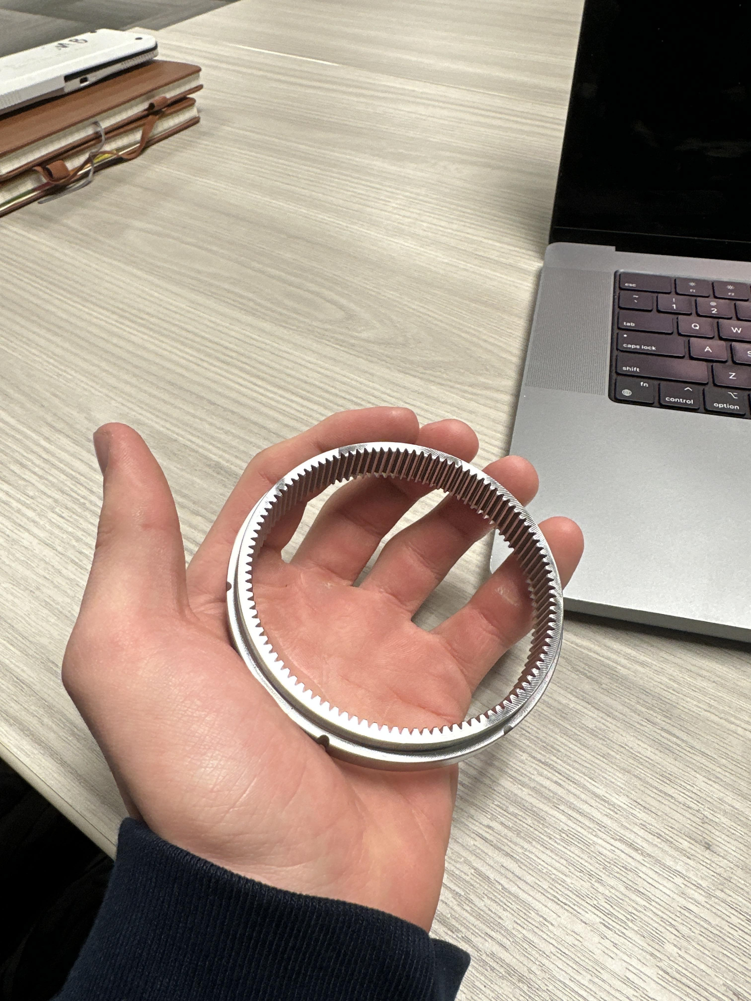
Drawing for ring gear G3
This part was, surprisingly, the easiest to manufacture. The profile was EDMed rather than shaped by a friendly supplier of ours, and all we had to do was clean it up after heat treatment and surface hardening.