This project was a collaboration with Chris Symonds (external/upright structures) and Luca Ranzani (the machinist I wish I could be). The end result of this project was a high-performance drive unit that the team tested and developed controls on for over three years.
Simulation: Reduction Ratio
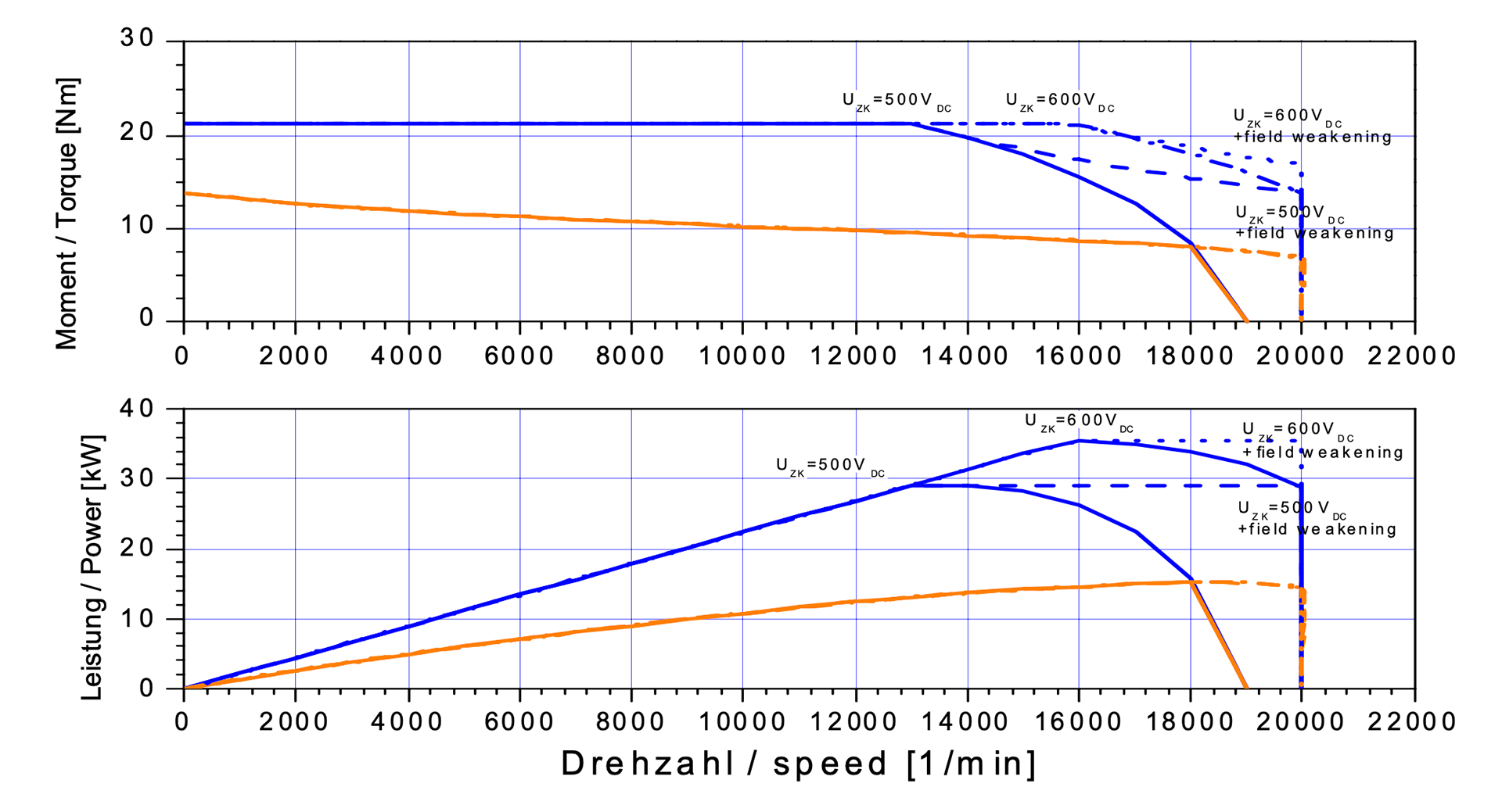
The first step in design was figuring out the targets for the system -- the team opted for the AMK student kit early on, as this was as "plug-and-play" as possible to start with and the company gave us a great discount. The supplied motors were AMK "DD5-14-10-POW-18600 B5" PMSM motors. With a motor assigned to each wheel of the car, this corresponded to a peak power of ~140 kW [188 hp]. Their performance chart looked like this:
With this decision made, I put together a lap simulator in Python to determine a sensible gear ratio. This was done by extracting track maps using historical IMU data (previous competitions) through a process of dead-reckoning. These track maps were then converted into a plot of corner radius vs. distance.
Combining this data with an estimated friction circle from the very same data, I developed a peaks-and-valleys iterative process for determining the maximum corner speed and brake points along each track. This works by assuming initially that a car is traveling at the absolute maximum speed with no longitudinal load transfer for any given curvature on the track, and then working the non-apex velocities down both forwards (limiting acceleration to achievable values given the previous state) and backwards (limiting braking to achievable values given the next state). This allowed me to include the effects of longitudinal load transfer in my simulation.
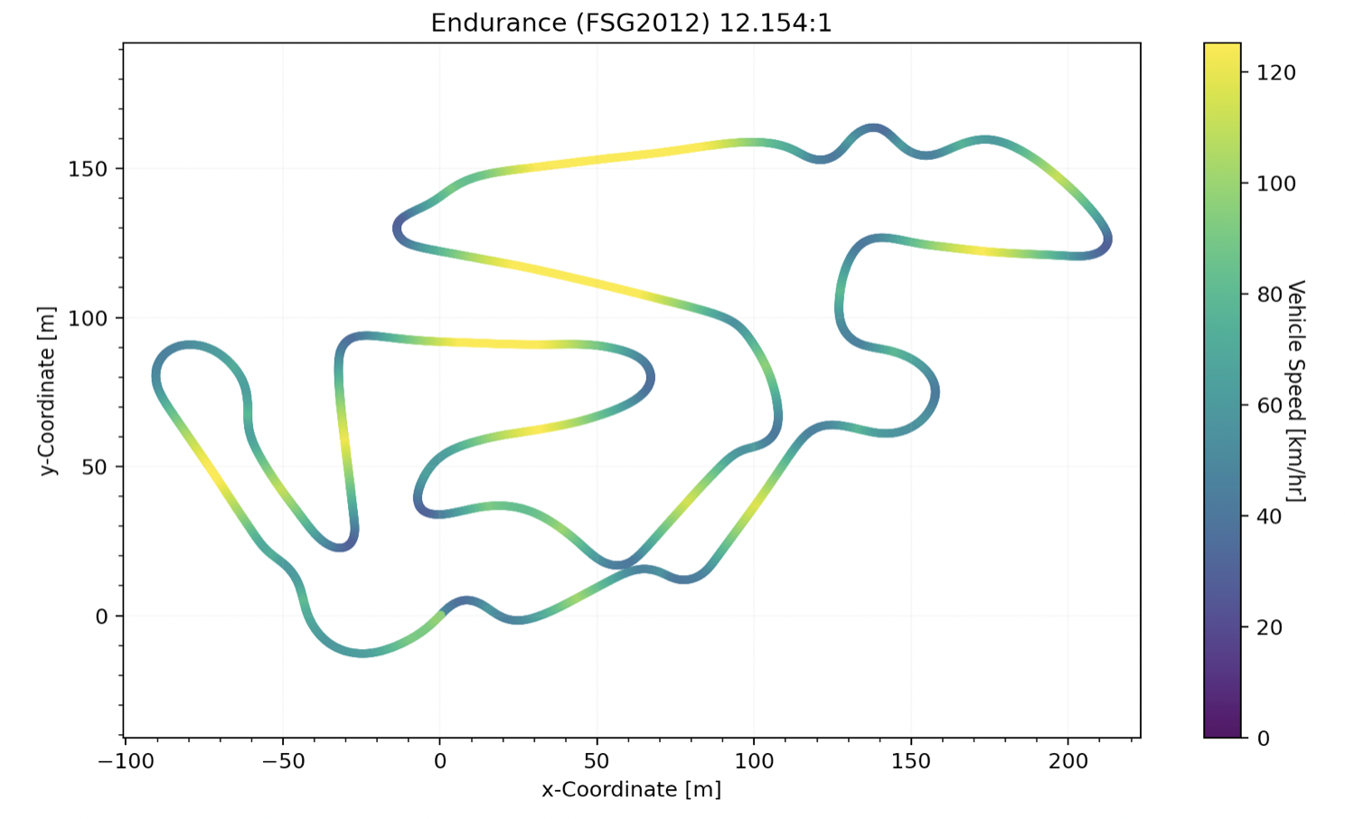
This process yielded velocity vs. displacement plots for various FSAE courses, from which lap-time could be extracted. An example of a simulated lap, plotted nicely, is shown below, starting at (0, 0) and moving in the +X direction.
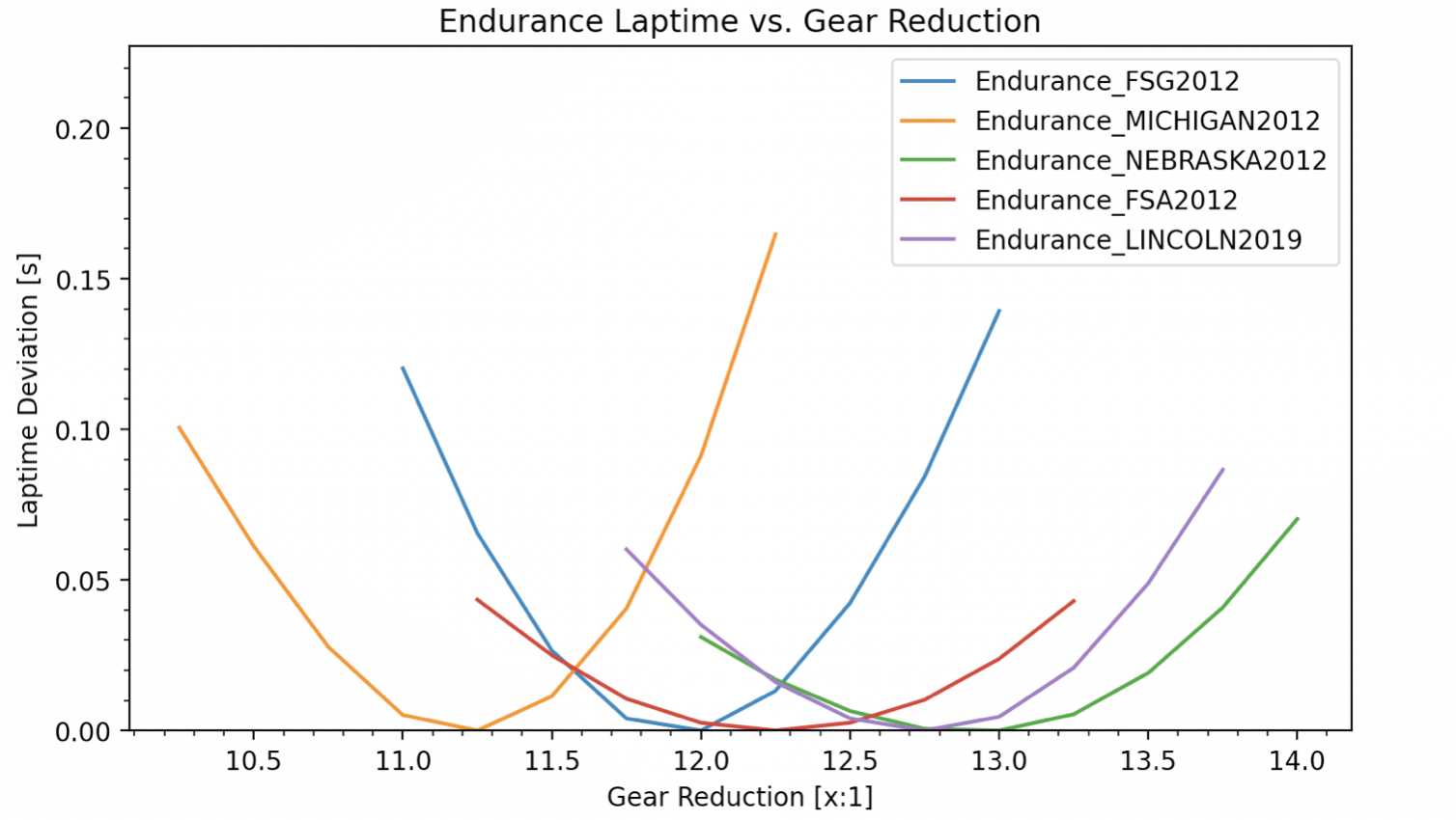
By extracting the lap-time for each iteration, I was able to perform a sensitivity analysis on a handful of the variables that I was guessing on vs. ideal gear ratio (next year's lap layout, bulk tire friction coefficient, CG height, mass of the car, etc.) I'm sure my ability to make a perfect model is flawed, but this at least gave me a good idea of where to start, design-wise, and what I was most sensitive to. Though impossible to post everything here, I more or less came to the following conclusions:
Things that "ideal" ratio was less sensitive to: Vehicle CG height
Vehicle mass
Tire frictional coefficient
Things that "ideal" ratio was more sensitive to: Track layout
Motor design/performance
Tire diameter
The sensitivity of the vehicle mass and tire frictional coefficient is surprising under normal circumstances, but I believe this is due to the choice of motors relative to the FSAE power limit of 80 kW. Because peak power out of the selected motors is nearly double this limit, there is very little time spent in a torque-limited zone. Low speeds are traction-limited, high speeds are power-limited. While increasing tire friction coefficient may make a shorter ratio more desirable for launches, the speeds at which you can actually use this extra torque grow smaller due to the persistent competition limit on power.
TLDR; the motors are over-powered. diminishing returns on shorter ratios even with the best tires. tradeoff between diminishing returns on launch torque and top speed. At the end of the day, once I had gone through nearly 40 sets of historical track data and gut-checking my ratio choice against that of similar competitors, I settled on a design range of 12:1 to 13:1.
Architecture
One of my goals for this system was efficiency and torque transparency in order to write good controls algorithms without a suite of ground-speed sensors.
Tires generally have a peaking friction response on dry surfaces and it is extremely important to be able to "feel" the response from the wheel in order to trim back power when slipping too much. Without dialed controls algorithms to properly distribute torque, it's of my opinion that we would benefit more from the simplicity and lightness of a RWD system.
As a result, I ruled out any kind of robotic-actuator style gearbox like a II-planetary, cycloid, or harmonic. This has the combined (and probably more important) benefit of not being incredibly inefficient and producing loads of difficult-to-reject heat. I also ruled out a dual-stage planetary for similar reasons, as I believed that the additional gear meshes would create significant amounts of resistance that would worsen the road "feel" and cut into our power.
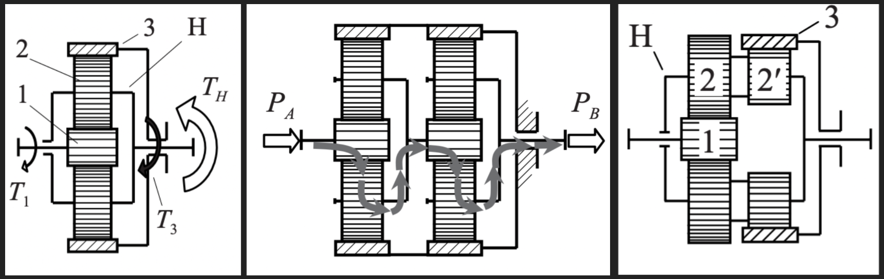
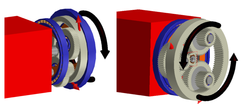
Left-to-right: "single-stage", "dual-stage", "compound"
Figures from Planetary Gear Trains (Kiril Arnaudov, Dimitar Petkov Karaivanov)
In order to get a suitable ratio for the events, a single-stage planetary or spur/wheel gear-set could not be packaged well. I instead opted for a compound planetary, which was not without its own drawbacks, but at least allowed the motor to be coaxial with a reasonably sized gearbox. This also happened to be the architecture chosen by the vast majority of our competitors, so it was probably a correct initial path.
Gearset Design
In order to select gear tooth counts and sizing, I started with a python script to generate every possible combination of gear teeth that yielded something close to what I wanted, and then dove through these massive excel sheets looking for what I considered to be the best configuration (all pinions stressed as equally as possible, co-prime numbers of teeth for even wear-in, etc.). I probably spent multiple weeks on this, going back and forth between excel, CAD, and Romax (with load cases derived from the simulation results above), until I found something that made me happy.
I ended up with a combination of 0.8mm module gears with tooth counts of (1, 2, 2', 3) = (21, 58, 26, 105), resulting in a 12.2:1 output ratio. This configuration has estimated dimensions of Ø110mm x 25mm [Ø4.3" x 1.0"], and an estimated mass of 0.70 kg [1.5 lb], as well as meeting the following design goals:
● Co-prime tooth counts for even wear and break-in
● No fewer than 17 teeth on any gear to avoid hobbing tooling issues
● Module must be common and large to avoid grinding tooling issues
● (Z_1*Z_2') + (Z_2*Z_3) must be divisible by 3*gcd(Z_2, Z_2'), so that all planet splines have the same clocking and all gears are interchangeable.
● All gears have sufficient rim thickness such that the failure mode is not rim fracture.
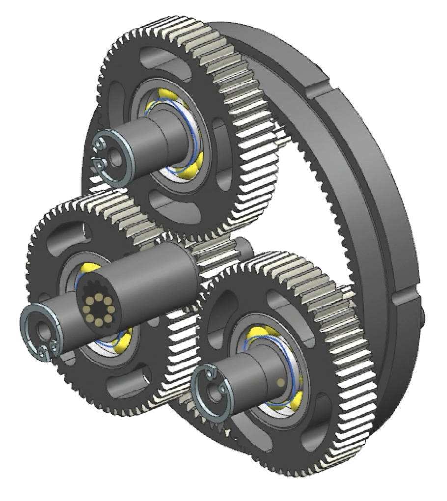
Romax Model of Compound Epicyclic
(1, 2, 2', 3) = (21, 58, 26, 105)
Carburized AISI 9310 was chosen as the material for all of the gears. In previous years, we had used nitrided AISI 4140, but the increased contact stress due to the small tooth size/count and higher speeds meant that the thin (and distinct in hardness) case would crack under the new loads. The gradual and longer hardness change from core to surface associated with carburizing performs much better under these kinds of stresses (see ANSI/AGMA 2001-D04).
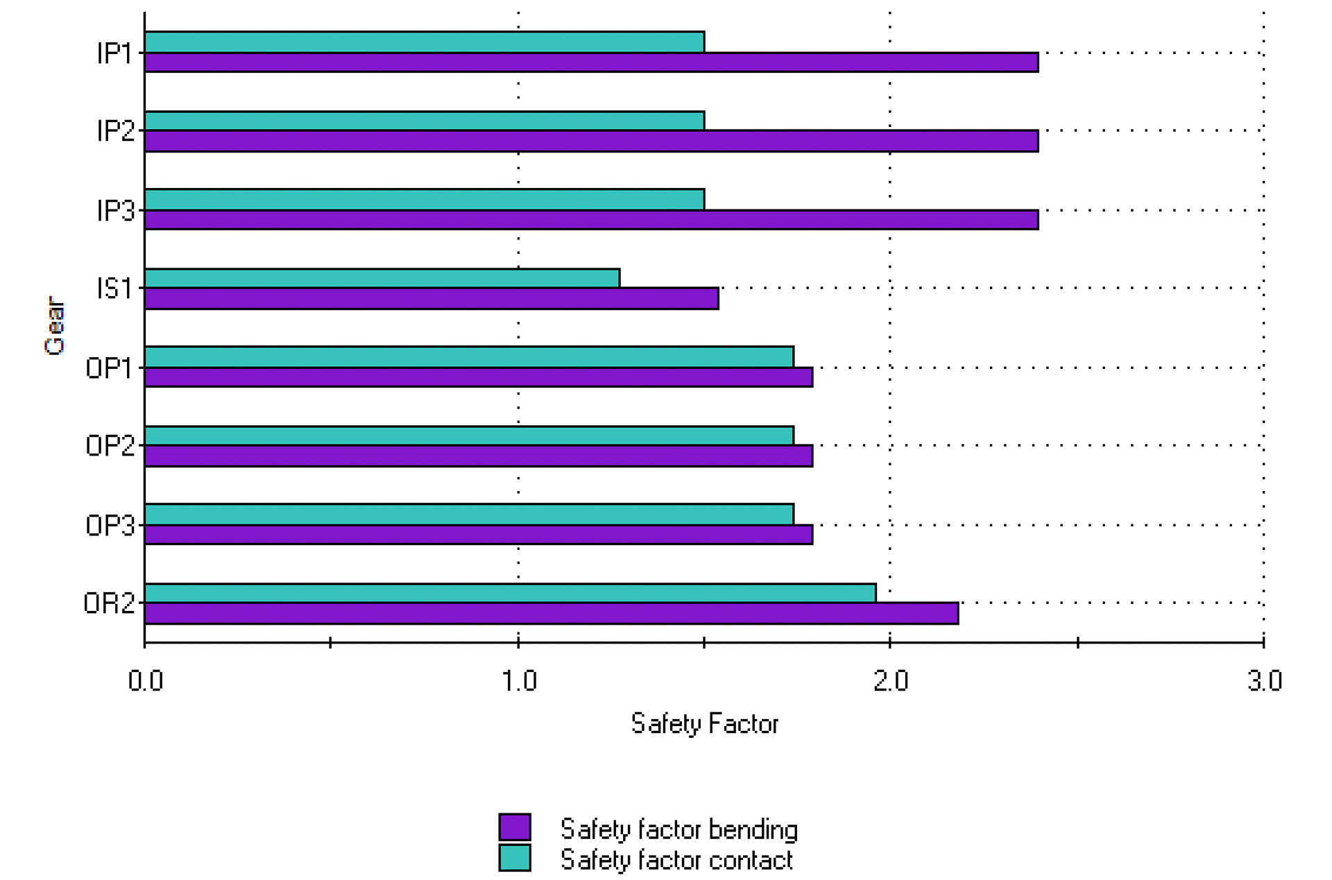
The safety factors against contact and bending are presented to the right, assuming around 25 hours of competition load cases and carburized AISI 9310. Being a first pass at the design, I wanted to make sure the system was reliable enough to collect data, so I tended towards the safe size on these values.
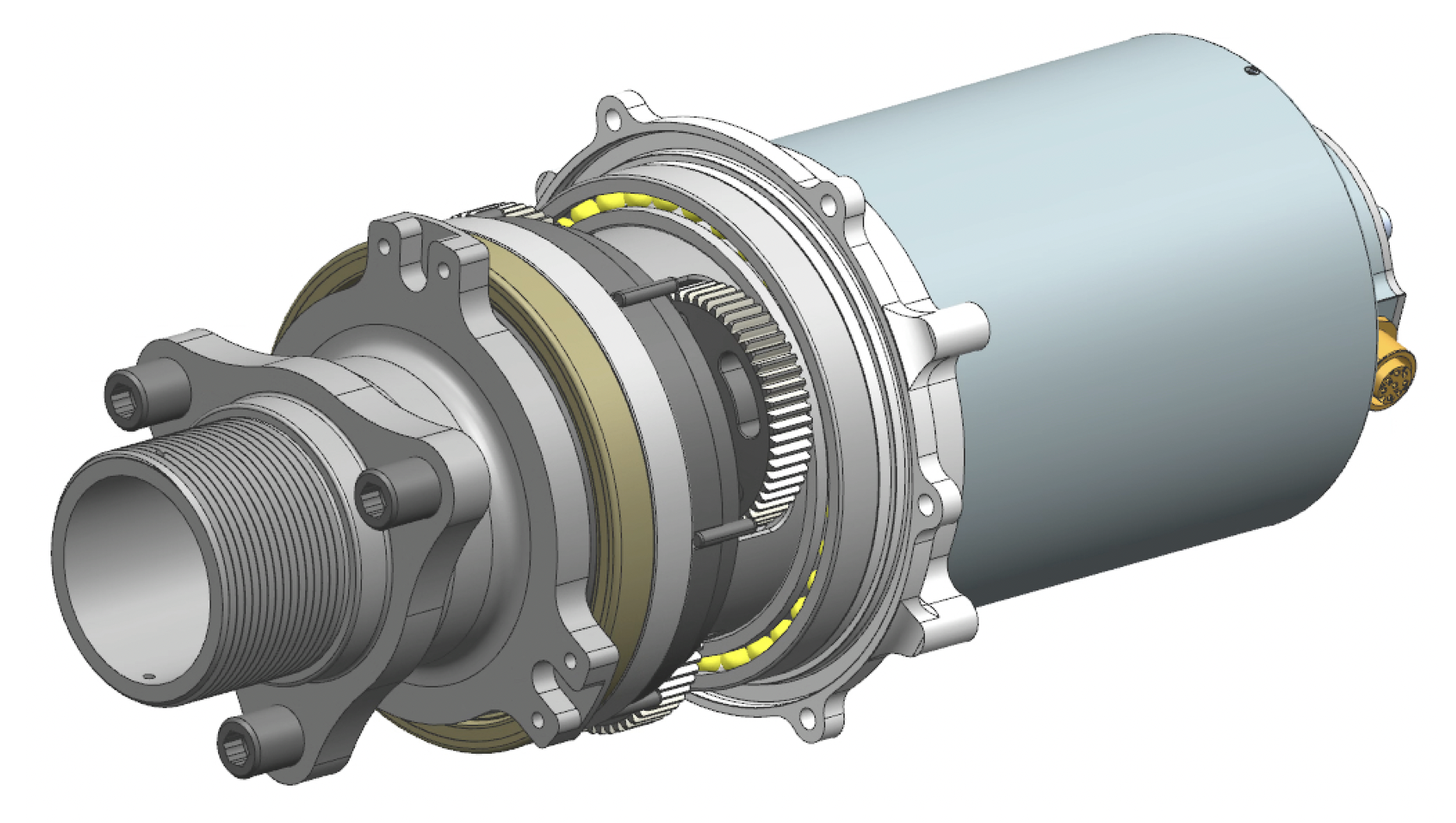
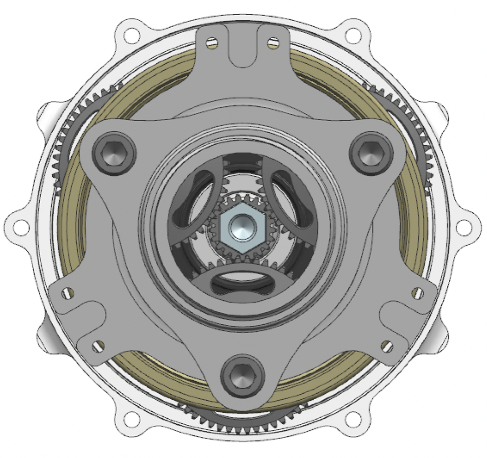
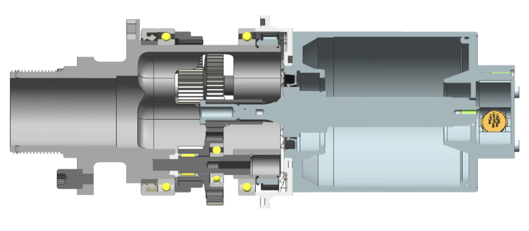
Detailed CAD Design
The gearbox is assembled into the upright of each wheel, with the spindle that supports the wheel serving a dual-purpose as the planet carrier. The angular-contact spindle bearings (SKF 71816) also act as planet carrier bearings. A custom M80-2.0 locknut pre-loads the two bearings.
The gearbox is immersed in an oil bath, which is sealed on the outboard side by a radial shaft seal (SKF 85x100x10 HMSA10 V) that rides on a modified needle roller bearing inner race pressed onto the aluminum spindle. The spindle is hollow, and there is a polycarbonate window bonded into the center that provides a sight-glass for visualizing oil level.
The planet loads are supported by two bearings, an SKF HK1012 needle roller underneath gear 2' and an SKF 6000 ball bearing underneath gear 2. The gears are supported axially by teflon spacers. The sun gear is cantilevered off of the 12-tooth input spline to "float" the gear in attempt to improve load distribution. Similarly, the ring gear is minimally constrained in the radial direction.
Feel free to look over some of the more interesting engineering drawings here -- hold your judgments, keep in mind that I had no formal GD&T or engineering drawing training when I designed this system.
Real-life photos!
Installing studs and retaining clips onto the spindles
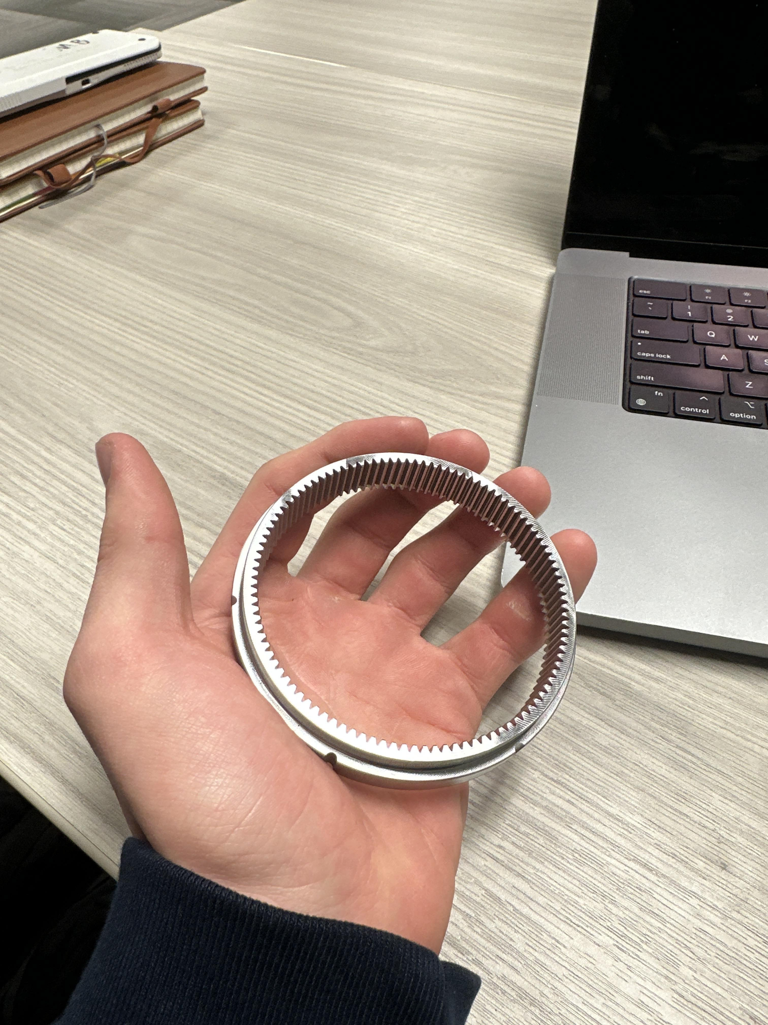
Ring gear post-hob, pre-carburization
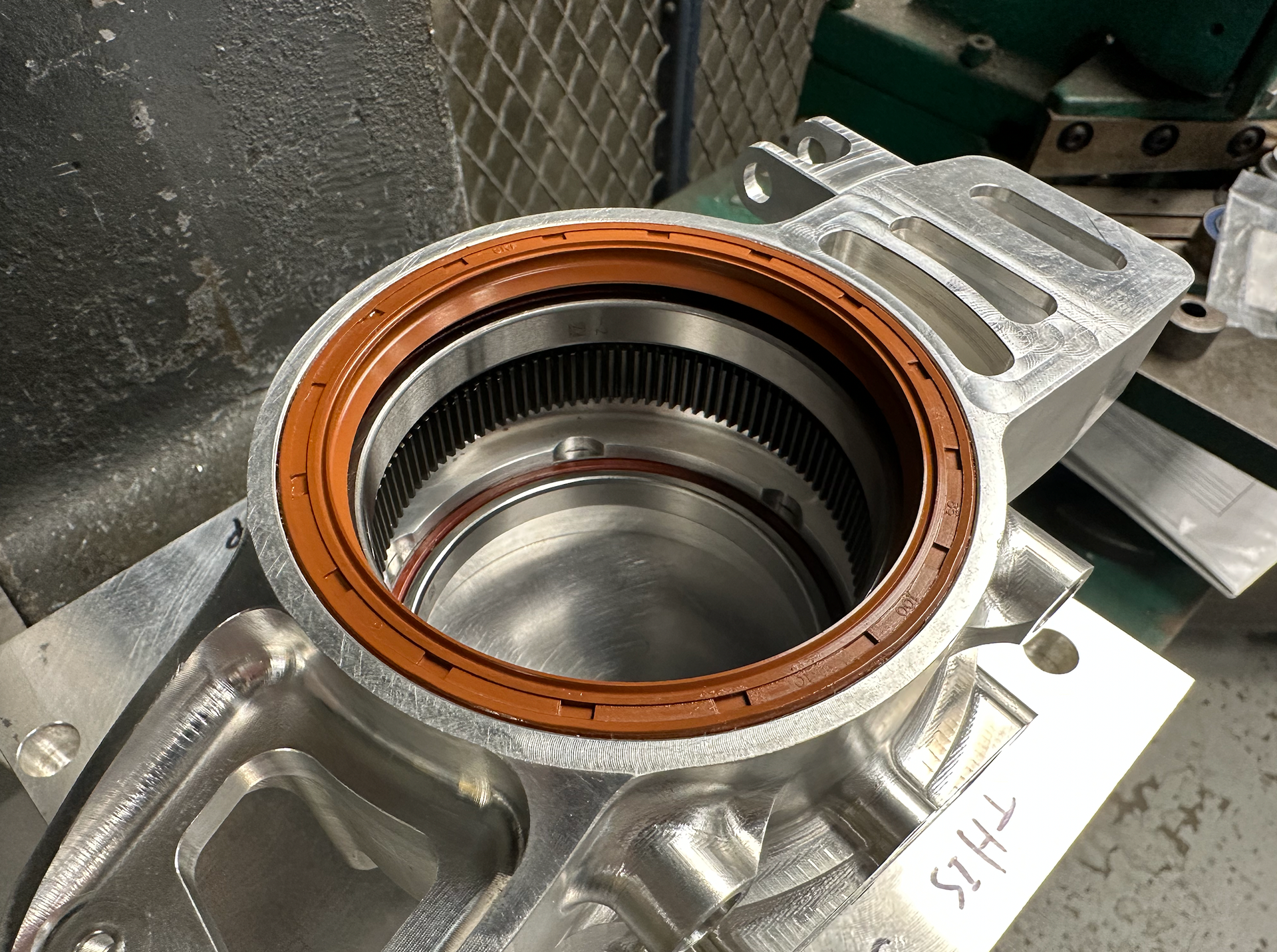
Pressing seals and AC bearings into the enclosure
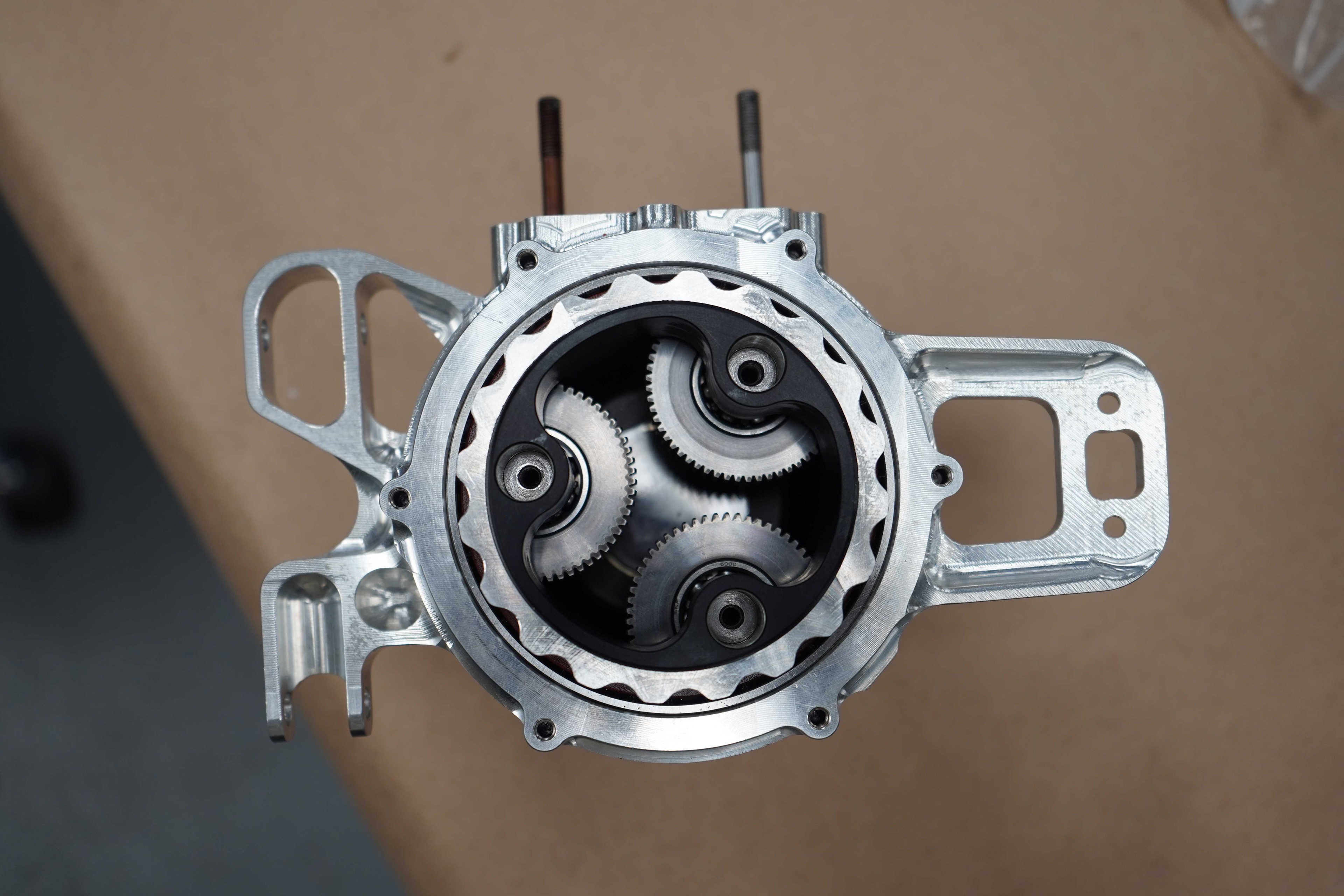
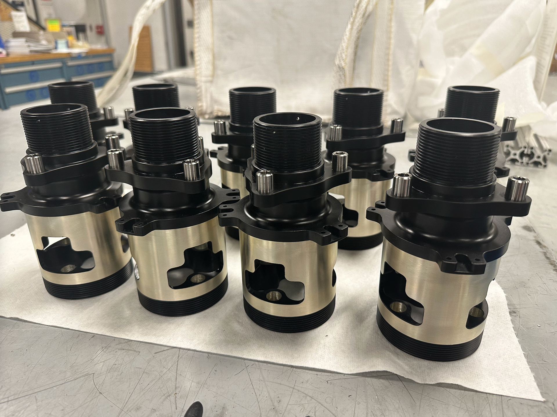
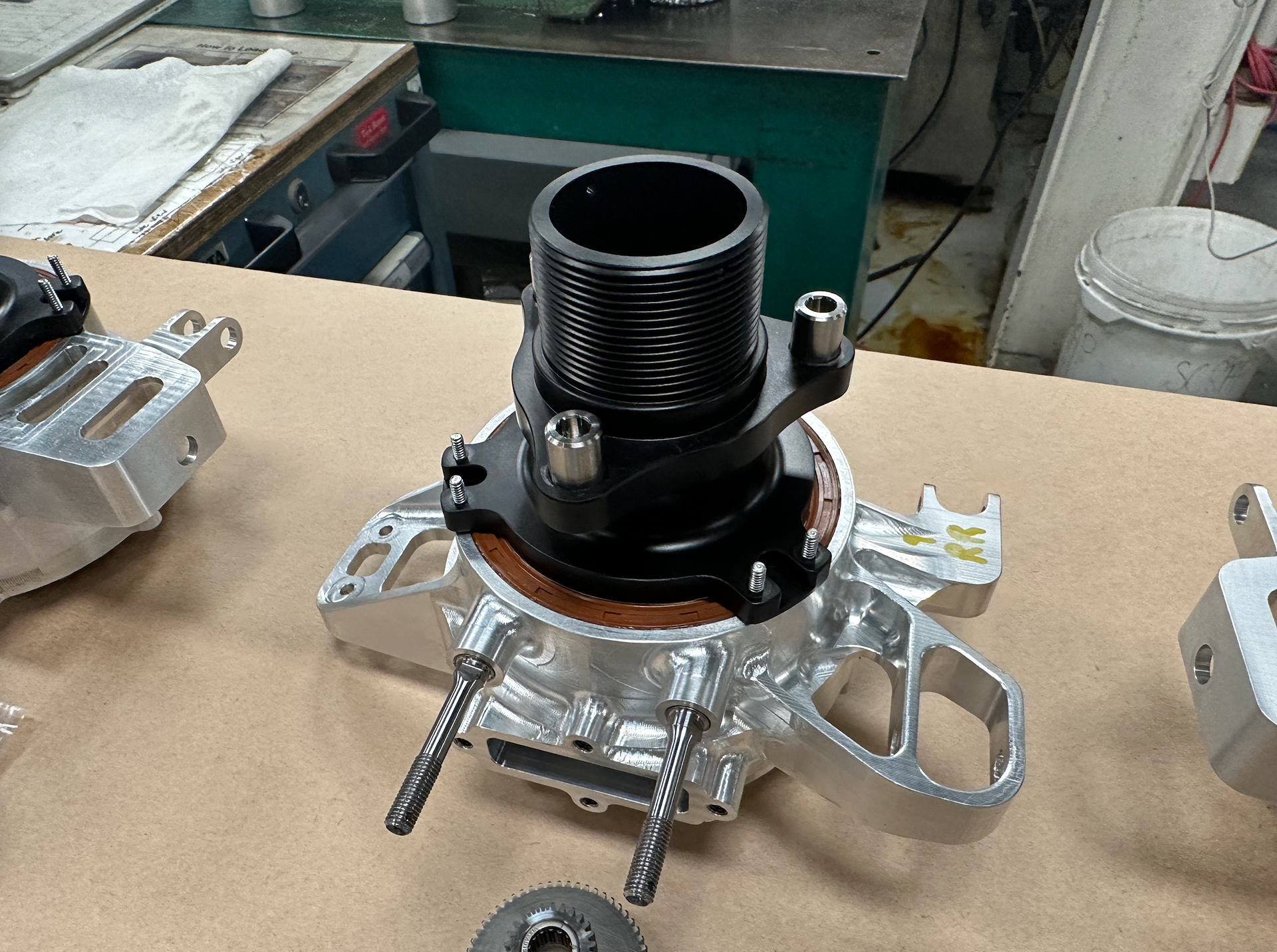
First drive unit assembled
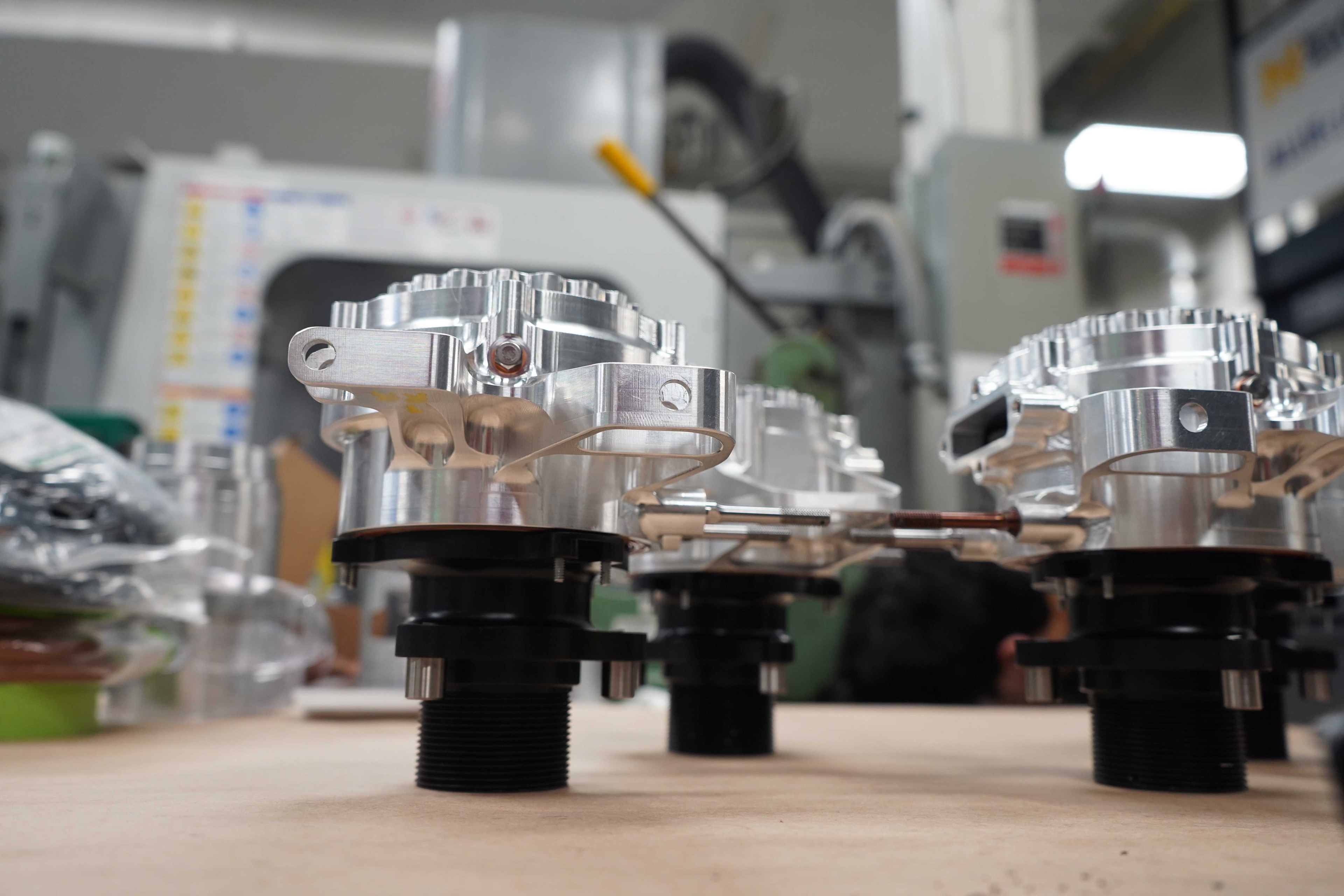
And then three more
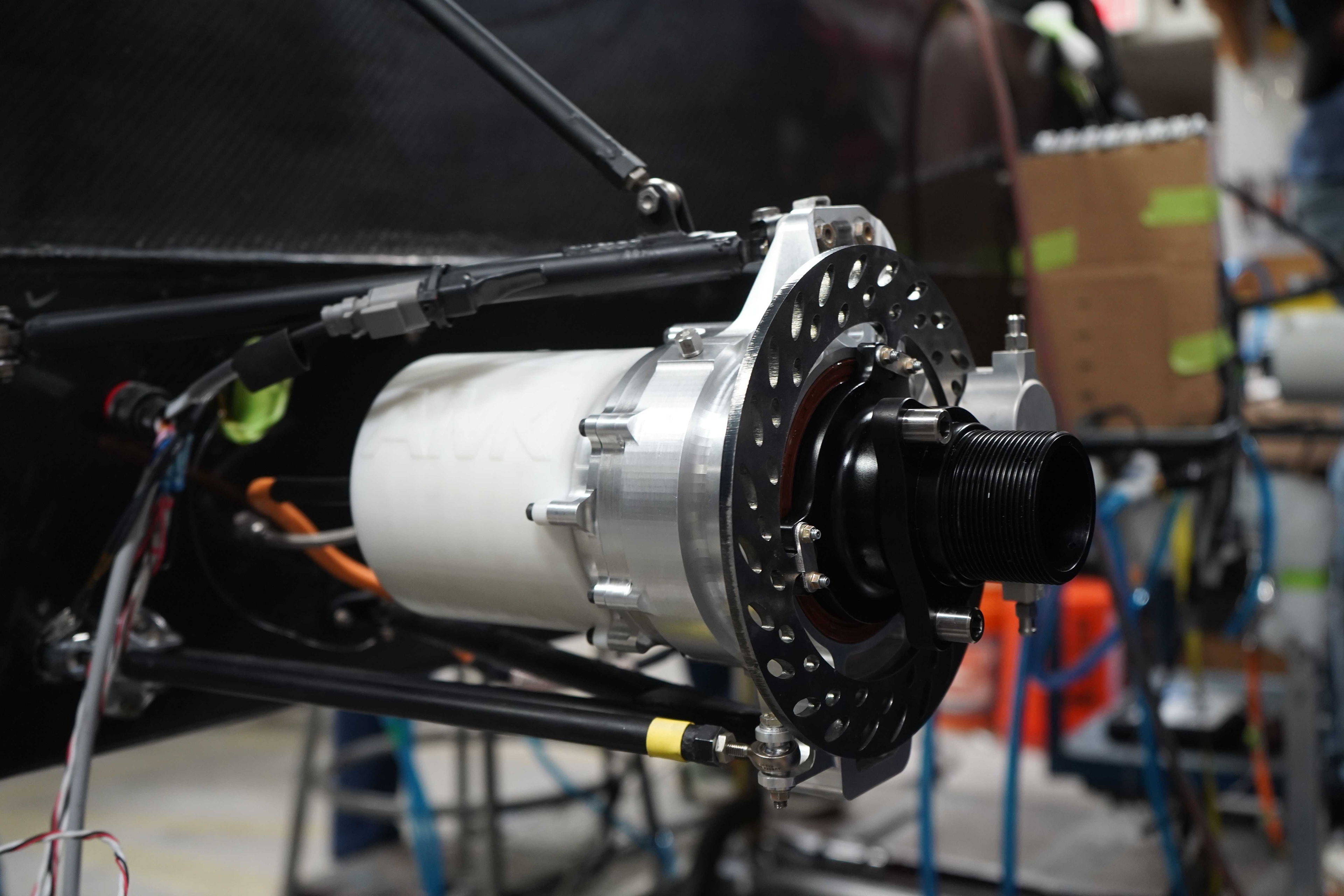
Drive unit assembled and on-car with brakes and motors
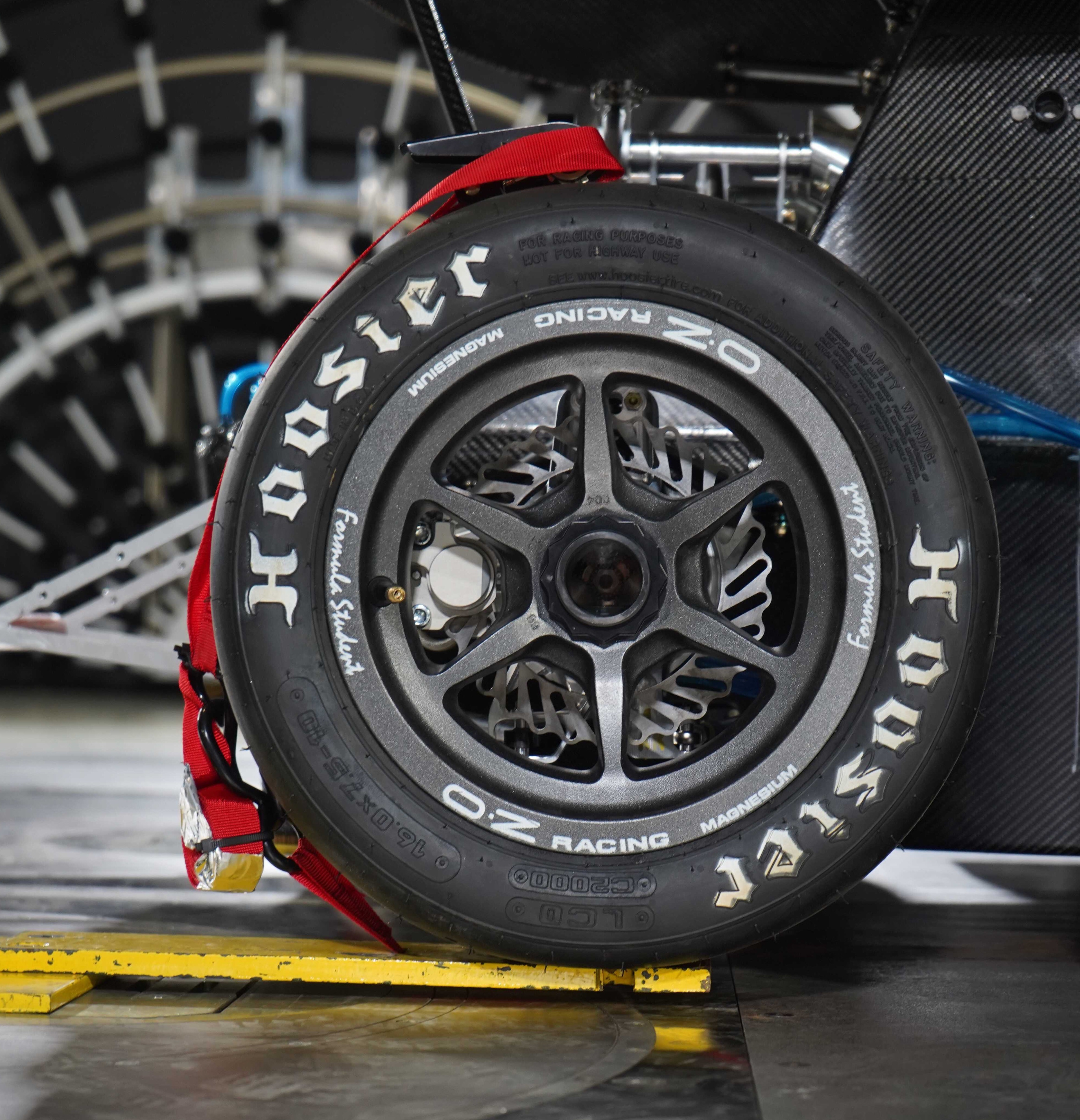
Shot captured during wind-tunnel testing -- view through the polycarbonate sight-glass